..................
........................................--- Re-wiring the Kera Jane ---
Here are some basics on how we re-wired the Mac. More detail will come later.
..........................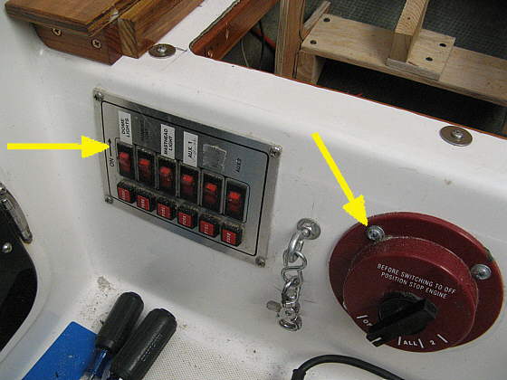
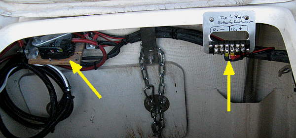
The left arrow points to the original breaker panel and the right arrow points to a off/1/all/2 battery switch that was added after we added a second battery to the boat. I didn't care for the breaker panel at all as it was starting to fail and I wanted any circuit "on" indicator lights in the boat to be energy saving LED's.
..........................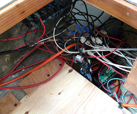
Here is the mess of wiring on the back side of the breaker panel. All of the white was stock and the rest of that birds nest was added by me :-(. We used the boat like this for the first year on our trips to Idaho, Canada, Colorado and Lake Powell in Utah.
Our original outboard's alternator didn't work, but we did run power from the gen-set and 40 watt solar panel on the boat forward to the 4 way power switch. After that year we replaced the Honda 8 HP with an electric start 9.8 HP Tohatsu extra-long shaft. We also added to the solar for a new total of 180 watts.
I didn't want to take a chance on burning the alternator out on the new outboard and also want to run the solar power through a MPPT charge controller. This meant new heavier wiring from the stern to the cabin area. I put in a new overhead console in plus new mast wiring and a computer/chart plotter/nav.station in so pretty much rewired the whole boat. The only original wiring now is from the cabin to the bow lights.
..........................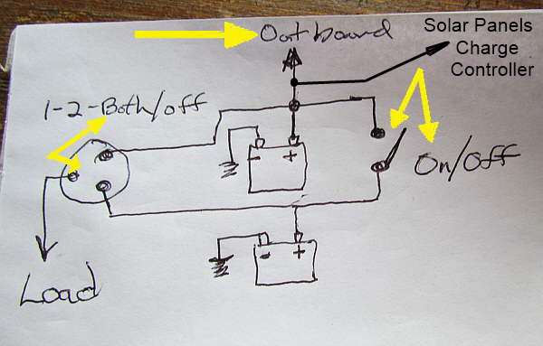
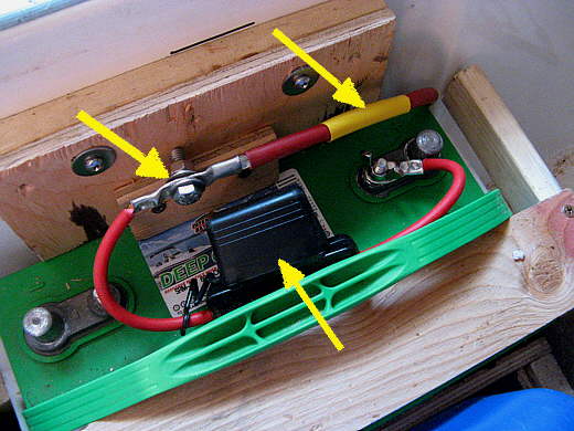
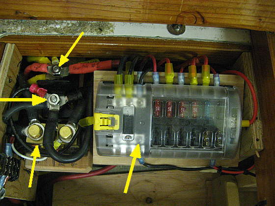
To avoid ever burning out the outboards alternator the wire to and from the stern for the outboard and gen-set, top arrow, goes directly to the top battery and are always connected to it. I have a heavy duty switch between the two batteries and usually keep it, right arrows, in the on position so that both batteries are charged jointly by the outboard and/or gen-set. The power from the solar array goes through a MPPT charge controller and then ties into this system where the stern power comes in above the top battery. So that output is going to either the top battery or both batteries.
The off/1/all/2 switch, left arrow, puts power to the load from either battery or both of them. Normally it is in the both mode. I only kept the option of getting the load from the bottom battery in the rare case the top battery had a major problem. At that time I could also easily take it out of the circuit by disconnecting the positive lead from it. Then I would have to leave the main switch in the #2 position so that the outboard would be connected to the second battery.
I don't anticipate doing that, but can if needed. Thus the main switch stays turned to the 'all', both batteries, position and the other switch stays turned 'on'.
Next I'll just highlight some areas of this mod and will add more later.
..........................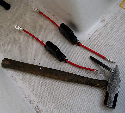
I made up two fused links for both batteries with large 60 amp spade fuses. All battery wiring and wiring to the stern is #4 and all the new wiring is tinned marine wiring.
..........................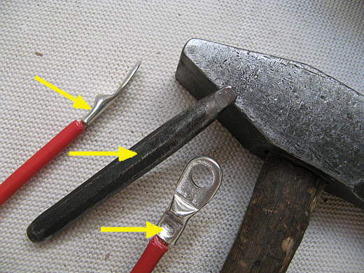
The chisel in the picture was ground to a blunt end and was then used to crimp on the cable ends. I put the cable ends on a thick metal block and then used the hand sledge and chisel to crimp them.
..........................
Here the fused link is attached to the battery and also to the #4 wire, top left arrow, going to the main distribution area in the cabin under the starboard seat. The bottom arrow points to the spade fuse holder. Various size fuses are available. Here 60 amp spade fuses where used. These are large fuses and not that cheap, but still reasonable. The top right arrow points to shrink wrap that....
..........................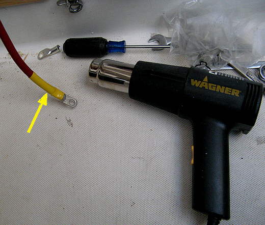
... was slid down and shrunk with a heat gun.
..........................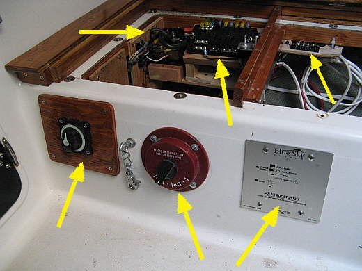
The main power distribution center is pictured above. The bottom left arrow points to the 'on/off' switch between the batteries. To the right of that is the 'load' switch or the 'off/1/all/2' switch. To the far right on the bottom is the MPPT charge controller for the solar array. There is separate wiring from the panels to this charge controller and it can be switched in or out of the system if needed.
The top right arrow points to a buss for 'data wires'. At present it is used to connect the NEMA data for our GPS position from the Cuda 350 GPS/fish/depth finder to the DSC function on our Standard Horizon Eclipse+ VHF with DSC. The DSC would transmit our present location over the radio if we were in a distress situation.
The middle top arrow points to the new 'spade fuse' type breaker panel. All circuit indicator lighting is now by the switches that operate any particular circuit. The top left arrow points to lugs for the main negative and positive wiring going to the main switches and batteries.
..........................
The top arrow points to the 'main positive lug' and the one below it is for the 'main negative lug'. All of the negative loads then go through the shunt (bottom arrow) which then sends the amperage being used to .1 of an amp to the amp meter in the overhead console. Voltage is also being read to .1 volt by another meter in the overhead console. The bottom right arrow points to the main breaker panel. In some cases loads from here go to the overhead console and the computer/nav. station on larger wiring and at that point....
..........................
.... go to smaller wiring which is then fuse at that point by glass cartridge fuses by there respective switches and LED indicator lights.
..........................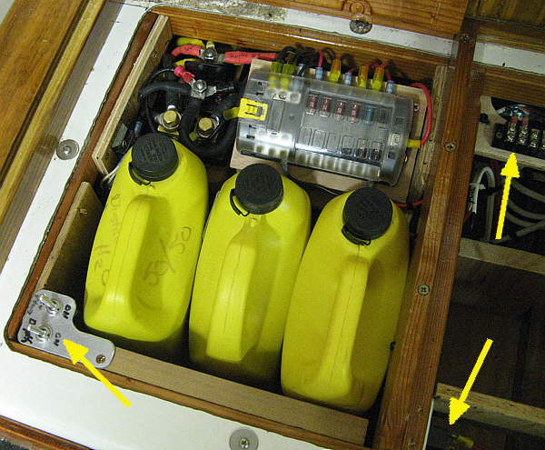
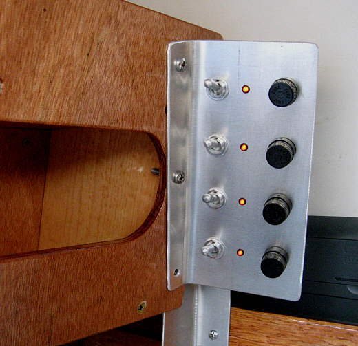
The bottom left arrow points to a switch that controls a 12 volt cigarette outlet by the sink and the other switch turns power on and off to the Cuda 350 GPS depth finder. The bottom right arrow points to a double pole switch that turns both the input and out put power from the MPPT charge controller. The top right terminal strip is for the data lines used for now with the NEMA info. The yellow containers are, part of our head and are color coded as to their use.
..........................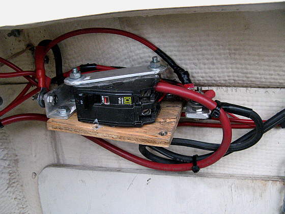
The power lines from the gen-set and outboard are also protected at the stern by this 50 amp breaker that is rated for DC as well as AC. One set of terminals are used for the main power to and from the stern area and the other set would turn off the 'field' on the alternator on the gen-set to help protect it if the breaker tripped and there was then no load on the alternator.
..........................
The left arrow points to the breaker and the right to a terminal strip for the solar array. One side is for the positive side and the other side for the negative. At this point only the wiring to the MPPT controller is attached. The 3 solar panels (40 watt, 60 watt and 80 watt) attach at the top of the strip.
We bought most of our wire, terminal ends, fuse panel, etc. from GenuinedealZ.com and what they didn't have we got from Defender Marine.
Hope this helps someone and more info will be added to the site later, Sum.