..................
........................................--- Portside Bilge Pump ---
Our Mac didn't have a bilge pump installed when we bought her and we sailed the first year without one. In 2010 we decided to install 2 pumps, one on each side of the cabin under the settees before going to Florida. I ran out of time and only installed one and I still need to do more to it later plus install the second one.
We have had some water under the seats after it has rained due to the chain plates. The purpose of these pumps isn't to remove that water, but to be there as a safety measure just in case we were to actually hole the boat somewhere. We hope this is a remote possibility, but none the less if it happened we would probably have our hands full trying to get the boat to a shoreline and bailing might be difficult.
The reason I'd like to have 2 is that the boat has the ballast tank in the middle, so the 2 low interior sides of the boat have a hump between them caused by the ballast tank. Right now with only one pump on the port side I fear that if we holed the starboard side that it might take on water and the boat might start listing to that side and raise the port side further and further into the air. If that happened then the one pump on the port side might never see the water until it was too late.
As I write this the boat is in Florida. I plan on either taking the second pump with us when we return and doing a temp install on the starboard side or waiting until later in the year when the boat returns home. That is more likely.
Also as you will see below I don't like the current way that the existing pump is activated. I just have a switch to turn it on or off. I want to also put a float switch in the circuit as if the boat was taking water and I turned the switch on it might pump dry and then burn the pump out before I turned the switch back off. With a float switch it would cycle on and off depending if there was water at the pump inlet. This would also be a good deal if we were away from the boat and it was in the water and started taking on water for some reason.
..........................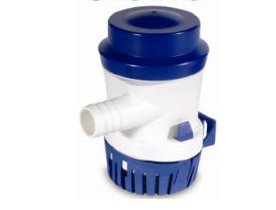
The pumps are both Shurflo 700 GPH (model #355-110-10) pumps like above.
..............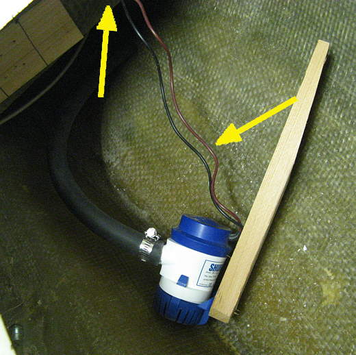
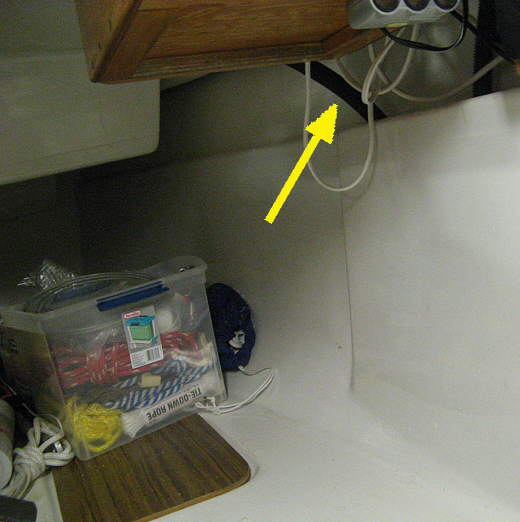
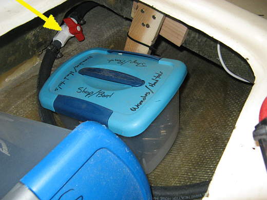
A piece of redwood (will change this to aluminum later) was cut to length and also with a taper at the top. The right arrow points to the wiring for the pump. There is a switch just outside the seat on the top of the aft side where the arrow is pointing...
..............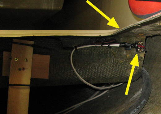
.... that for now controls the pump. The right arrow above points to the wiring side of the switch. Later I'll replace this switch with a single pole double throw center off switch. On one way will turn the pump on. The other on position will turn the pump on only if the float switch is on. I plan on taking one of those back to Florida and wire it in as that would be easy and fast to do.
..............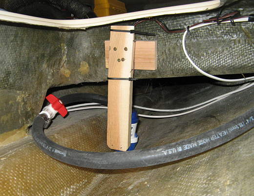
The horizontal piece of wood was screwed to the side of the seat with screws into it from the other side. Then the upright was screwed to it. The taper on the upright was cut since the side of the seat slopes so that it would release from the mold when the inner liner was made. The zip ties on the upright hold the wiring. You can also see a valve I put in the line. Probably doesn't need to be there, but I put it in. Also the pump is not quite at the lowest part of the bilge. The bilge is a little lower forward of the mounting. I didn't want to put it there as we have storage containers in that area. That is where the rain water accumulates and we just sponge that out. To the left of the pump is the water ballast tank that stops water from going for side to side in the boat until the water gets high enough to cross it. Also the cockpit sole is bonded to the top of the ballast tank that also stops and water in the bilge from going straight across from side to side.
..............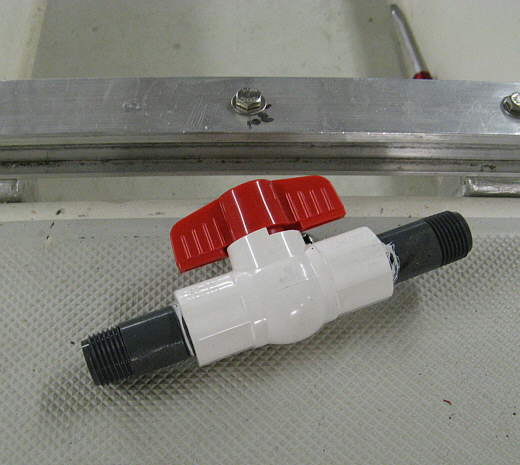
The valve is just a ball valve from the hardware store with plastic nipples screwed into it. The discharge hose slides over the nipples and is held on with hose clamps.
..............
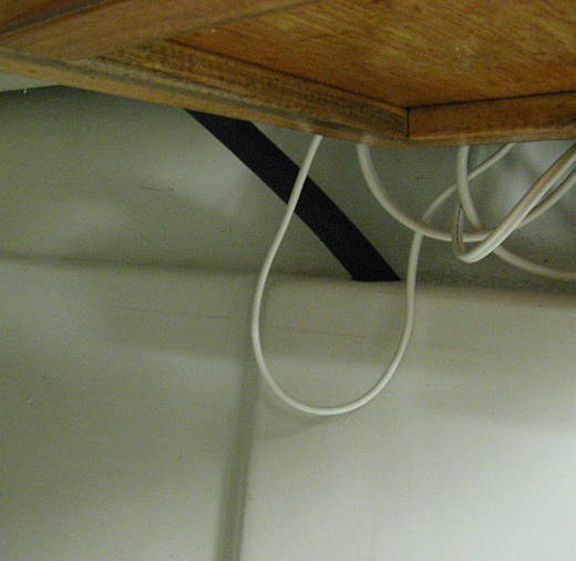
The discharge hose leaves the bilge and goes up the port side of the hull next to the inner liner where the aft bed is.
..............
It exits the liner up where the bottom liner meets the top one.
..............
Excuse the wiring. I was still finish wiring from the main breaker panel by the head to the computer area. The bilge pump is wired from this area.
..............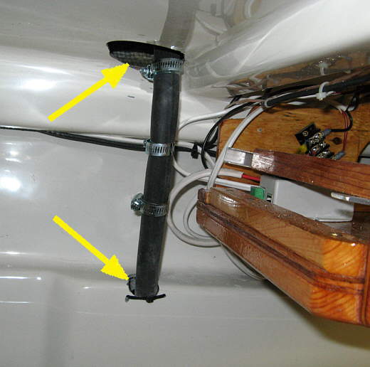
To the right is the wiring and mount for the ship's computer. Holes were made in the lower and upper liners, arrows, with a carbide rotary bit in an air tool. The hose clamps help to keep the discharge hose from collapsing since the bend is pretty tight in it in this area.
..............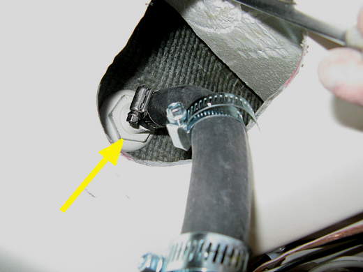
The discharge line attaches to a thru-hull tailpipe on the side of the boat after passing through the top liner.
.................................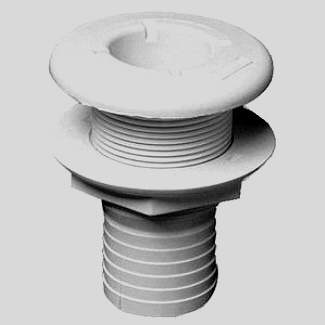
The marelon thru-hull tailpipe is a Forespar 906024. I used 3M 4000 sealant to seal where it goes thru the hull.
..............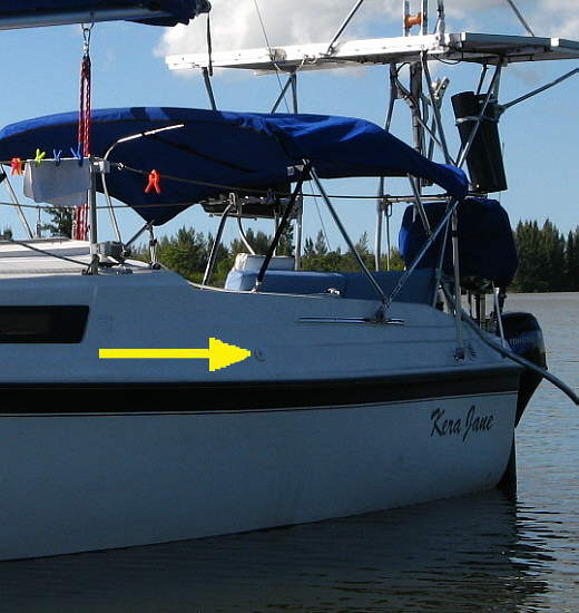
The thru-hull exits the boat above the rub rail. This high exit will mean that the pump might not pump as many gallons per minute vs. being lower as the head is more, but up here it shouldn't ever go under water heeling with us sailing the boat. Since it is so high I don't think the valve below is really needed. I also have to admit that as of the time of writing this I've never actually tried pumping water with the pump. I'll a pump in a bucket at some point with the same head and see how it does. According to the specs this pump should pump 700 GPH @ 0 head, 600 GPH @ 3 feet and 500 GPH @ 6 feet, so I'm guess it should do over 500 GPH. With a second pump on the starboard side that would be over 1000 GPH if they both were in the water.
..............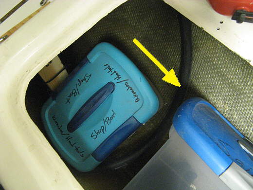
Here you can see two of the storage containers with the discharge line between them.
..............
Another view of where we would have to reach to to turn the valve on. It kind of looks like it is back there, but it isn't hard to get to at all. Still debating if we will just leave it open all of the time or not.