..................
...........--- Removable Mount for Tohatsu 9.8 HP ---
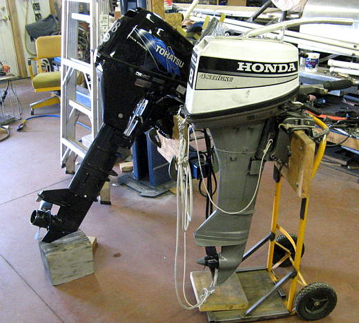
Out 26S came with the 8 HP Honda in the next picture. Except for our first outing where it wouldn't start it had proved to be a good outboard, but we decided we needed to replace it.
We are moving into our late 60's and I'm still able to pull start it, but Ruth can't. After my accident on Lake Powell where I fractured my shoulder and we had to lay up in the same canyon for a number of days until I could start the outboard we decided for safety reasons alone we needed an outboard with electric start. This way no matter what the situation Ruth will be able to start the outboard. She is at the tiller or the outboard most of the time we are underway, so using it is no big deal for her if she can start it.
We researched Honda, Yamaha and Tohatsu/Nissan (same outboard) and decided that the Tohatsu was the best for the buck. Our Honda was a 'long shaft' model and although it was just fine for all of the sailing we had done we decide on buying the Tohatsu in the 'extra-long shaft' model.
We made this decision based on a couple things. The first was that if we did any ocean sailing we would have the benefit of the outboard being further in the water if there were swells to deal with. Second was that even thought the Tohatsu was within a couple pounds of the Honda it was larger in physical size. It won't rotate as far in the motor well before hitting the sides. I figured that if I made a motor mount that was 5 inches higher then for most of our sailing the prop would be in the water the same depth as the Honda long shaft, but being 5 inches higher an a little further back on the mount it would now rotate fully and as an added bonus the controls would be up higher and closer to Ruth when she is sitting on the lazarette during anchoring and docking maneuvers. So this build page will document the new higher motor mount.
.......
Above you can see the difference in the shaft length between the Honda long shaft and the Tohatsu extra (or ultra) long shaft. The lines on the Honda were to make raising it an easy deal and will be moved to the Tohatsu.
.......
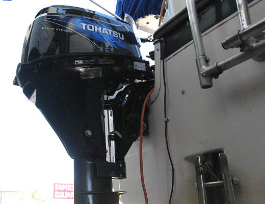
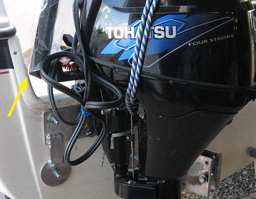
Here the 9.8 HP is mounted on the transom in the stock location. If you want the extra long shaft it is only available in the 9.8 HP model. Both the 8 and 9.8 HP are offered in electric start and in a long shaft model.
.......
I was able to located the outboard on the transom so that the tiller/throttle arm would just barely clear the port side of the motor well, but....
.......
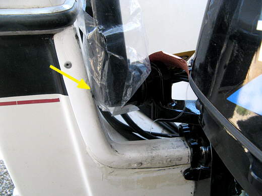
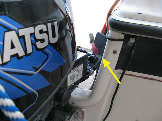
...... the shift linkage would hit on the starboard side while in the forward position. Still you can steer the outboard some and also using the tiller you could manage to maneuver pretty well in a tight situation. Out on the lake we always just put the outboard straight ahead and do all of the steering with the rudder.
.......
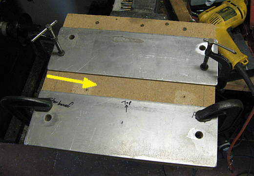
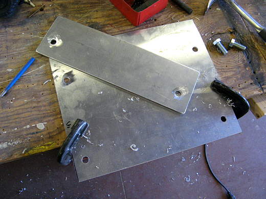
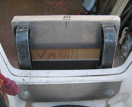
I made some plates to spread the load of the new mount over the outside and inside of the transom. The top plate will go on the outside of the boat and the bottom plate will go on the inside of the lazarette. I located them where I wanted them and drilled holes in the particle board, so that I would have a template for the rest of the plates.
.......
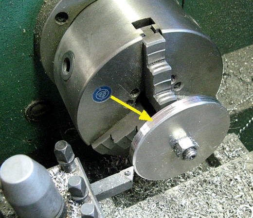
Here I'm using the lathe to make two circular plates for the outside. It is hard to see, but the arrow shows the the parting line between the two plates.
.......
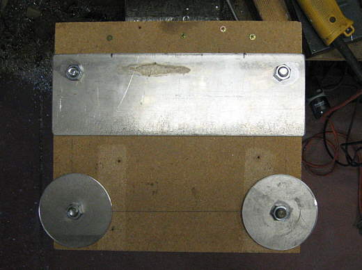
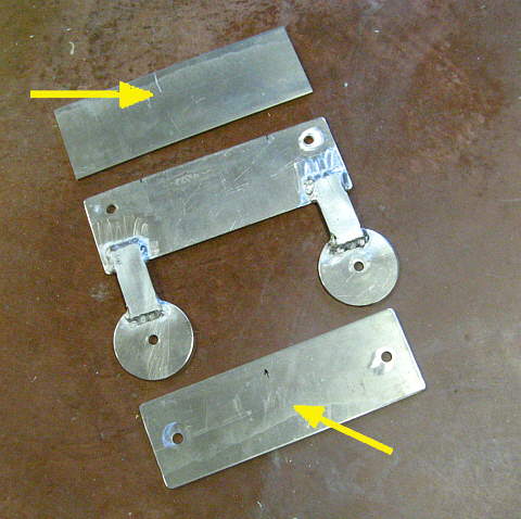
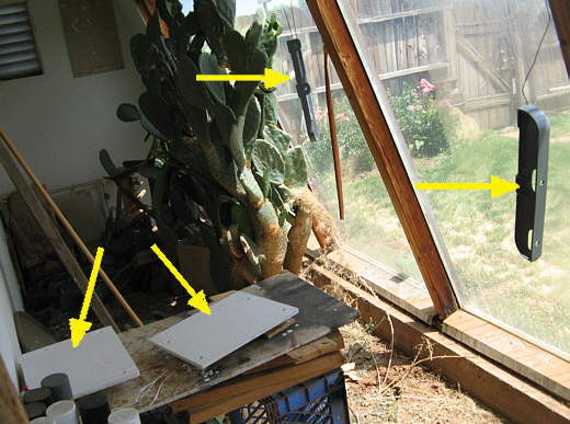
Using my template I place one plate at the top and the two circular ones at the bottom and...
.......
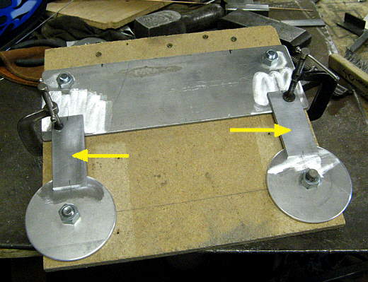
....cut a couple pieces of flat strap to connect them and then......
.......
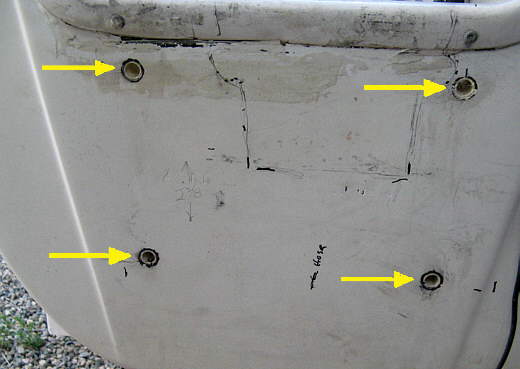
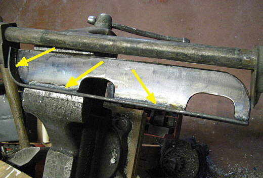
..... welded all of that together. The very top plate (top arrow) will end up going inside the motor well at the top. The bottom plate (bottom arrow) will go inside of the lazarette on the inside of the transom adjacent to the circular plates that will be on the outside of the transom.
.......
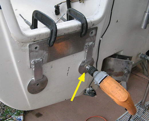
Here the outside plates are clamped into place and then the holes were drilled for 1/2 inch bolts through the transom into the motor well on the top and the lazarette on the bottom.
.......
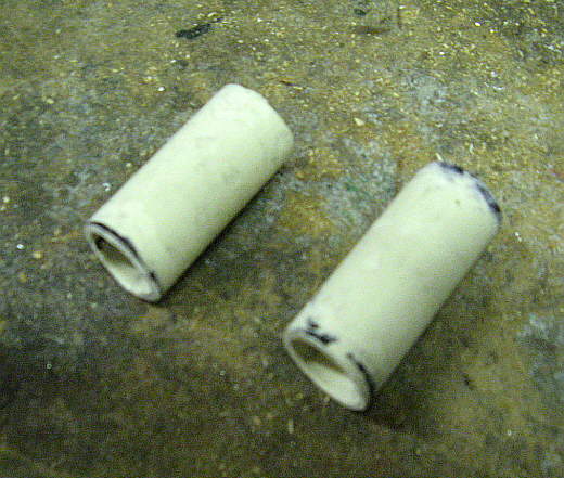
I removed the plate off the stern and then drilled the holes out oversize so that these pieces of CPVC pipe would fit in them.
.......
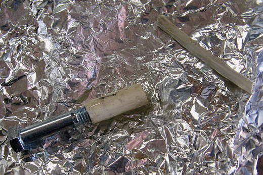
Some epoxy was mixed up on the tin foil and the pieces of pipe were coated and put into the holes on the transom.
.......
Here you can see the CPVC inserted into the mounting holes.
.......
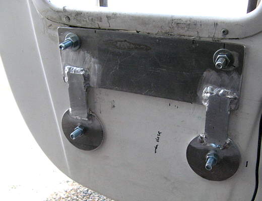
Next the mount backing plate was bolted on with another backing plate inside of the lazarette at the bottom and....
.......
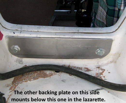
..... the above plate inside of the motor well. The bolts are all long for a reason that will soon be evident.
.......
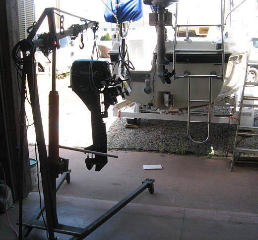
I had hernia surgery a couple weeks before this, so I made sure to use the 'cherry picker' while moving the outboard around.
.......
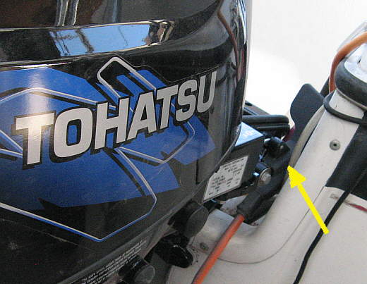
Here the outboard is mounted on the plates and since they move it back slightly the tiller arm clears a little better and....
.......
....the gear shift comes closer to clearing, but I want better than this.
.......
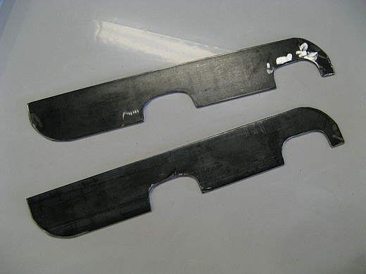
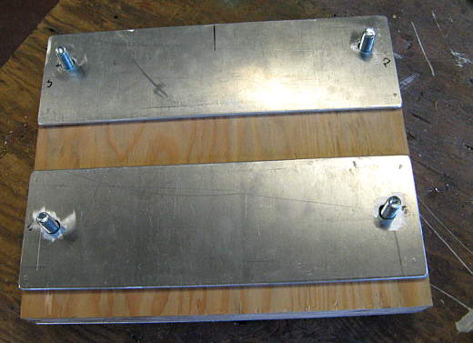
The reason the bolts stuck out was for the new mount to have an attach point. It was started with these two pieces of flat bar steel. I would have like to of made of out of aluminum, but just didn't trust it for this application.
.......
Next these two pieces were cut out from more strap.
.......
They will be welded to the two vertical pieces.
.......
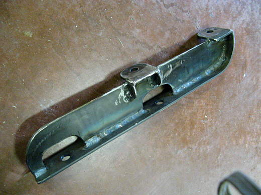
I welded the long flat pieces to them along the bottom up to where the bend was and then put the two pieces in the vice and first beat the one piece around the bend with a hand sledge hammer and then used the pipe clamp to pull it the rest of the way and hold it while it was welded around the bend.
.......
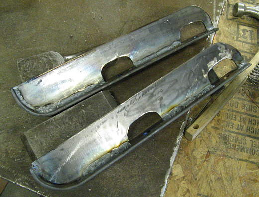
Here the two mounts are in the process of being welded for the entire length on both sides. This is so much for strength as to avoid water from entering the weld and rusting it later down the road.
.......
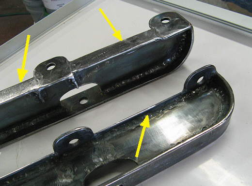
Next two tabs were welded on and ....
.......
... the one towards the middle was gusseted on the one side. Then....
.......
... more flat strap was welded between the tabs and down around the other bend.
.......
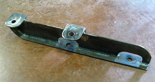
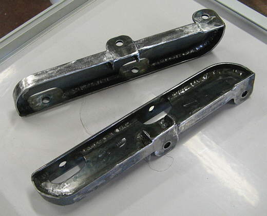
The resulting pieces are very strong to say the least.
.......
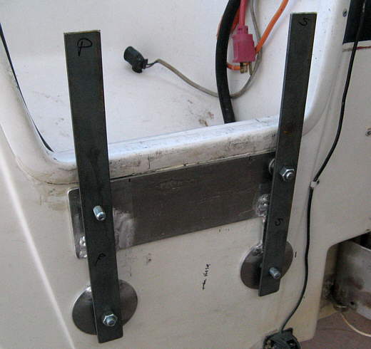
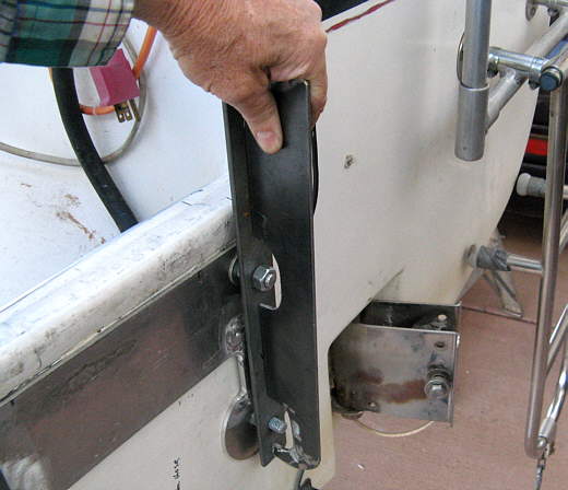
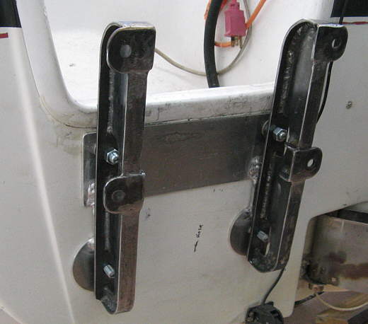
Here they are bolted to the transom of the boat. The aluminum backing that was put on first will stay on the boat regardless of if the motor is down low on the transom or up higher on the mount that is being made.
.......
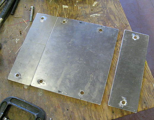
The plate that the outboard will attach to was made from sheets of aluminum on both sides with 3 pieces of 1/2 inch marine grade plywood between them.
.......
Above are the three pieces of aluminum. The large one will be at the back and the other two will face forward. Two large ones could of been used, but this is what I had available.
.......
Here you can see the two smaller ones and the ....
.......
...one larger one with the 3 pieces of plywood between them.
.......
A view from the boat.
.......
I gave the metal pieces 2 coats of epoxy paint followed by 2 coats of white urethane paint. This should hold up quite well. Each mount weighs 4 lbs. so not as much as they look. I also painted the 3 pieces (2 shown) of plywood with a good exterior deck paint.
.......
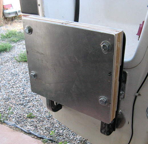
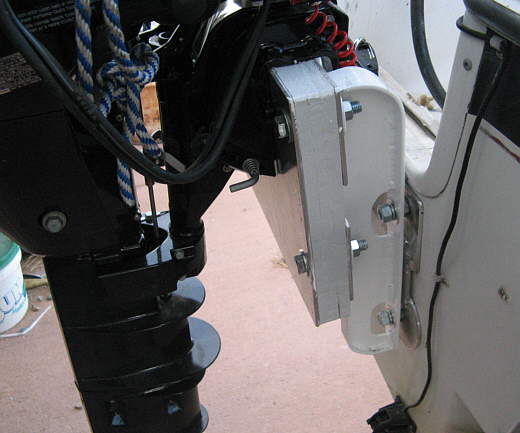
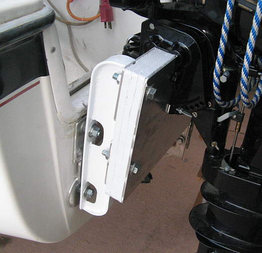
Here is the finished mount looking at it from the starboard side and....
.......
..... from the port side. I'm real happy with how it turned out and only time will tell if it does the job.
.......
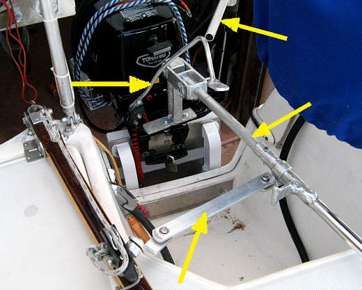
Here is a view from the cockpit and it shows the other mods done to the new motor to make it easier for Ruth and/or I to control it while also manning the rudder tiller.
The top right arrow points to an attachment to the twist throttle. The upper left arrow points to the extension for the shifter. The bottom right points to the new outboard tiller handle that extends into the cockpit. The bottom left arrow points to a linkage that can be put on or removed in less than 15 seconds. Once in place it allows the outboard to track with the rudder for maneuvering in tight locations. At the moment I have 3 videos up showing it in use....
If I don't have the other outboard mods up when you read this hopefully I will soon,
Sum