..................
..........................................--- Solar Panel High Mounts ---
.......
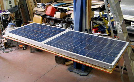
NOTE: Above is the latest panel configuration, which is now 200 watts vs. the 180 watts explained on this page. We broke a panel at Marco Island when we hit a piling. When we replace it we came up with a different combination of panels and now have the 200 watts ( a 40, 60 and 100). I also reconfigured how they mount so that they don't hang out so far and hopefully that will pay on in that they won't hit anything. At some point I'll document the change that also features a change that allows the 40 watt panel to rotate to some degree.
===================================================
Needing a dependable supply of electricity for my CPAP machine for sleep apnea I had built a gen-set for the boat in 2009. The CPAP uses about 40 amp hours a day. Later we added a 40 watt panel and really like it as then we didn't have to run the gen-set as much, about 15-20 minutes a day on the average. Then we added a 'real' frig to the boat and with it wanted to add more solar panels for the frig, CPAP machine and a 12 volt computer/chart plotter I was building along with the other normal electrical needs.
Along with the 40 watt panel we had I thought I could find room for a 60 and 80 watt panels. First they were going to mount back where the 40 was and I was going to move it to the cabin top. Then I read about guys mounting panels on an arch over the stern and started to look into that. Pretty soon I decide that was the way to go and with it I could keep the 40 back there along with the new 60 and 80 watt panels.
This mod wasn't going to do anything for the boats looks, but we were more concerned with increasing our cruising comforts for very extended trips on the boat. Longer than we had been taking, so the looks took a second to function.
.......
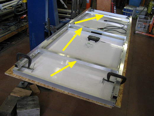
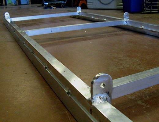
Here the new 60 and 80 watt panels are laid down on their faces and I've already made the long supports that go under the panels and I'm cutting the cross-members (arrows).
.......
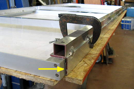
The long mounts were clamped to the sides of the solar panes with a spacer wedge (arrow) to give a little clearance. Then the cross-members were cut and laid in and then....
.......
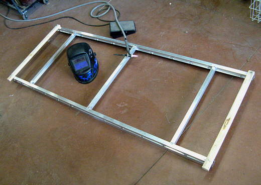
......tacked in place on the floor. Notice that temp wood pieces were used on the ends to hold things together until the cross members were tacked into place.
.......
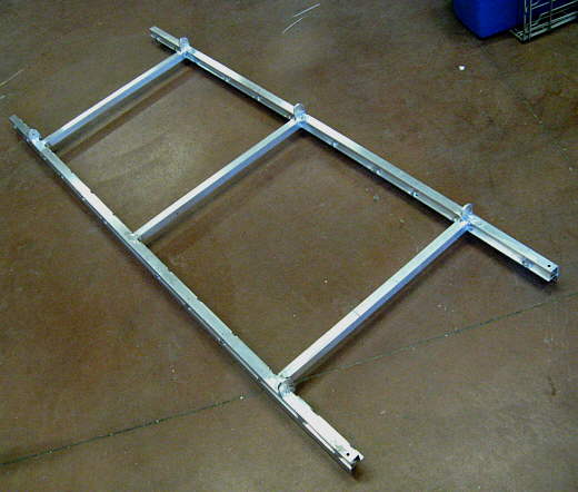
Here are the panels on the frame. 2 holes per side, per panel were drilled for 1/4 inch bolts that hold the panels to the frame.
.......
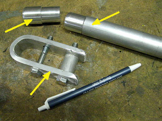
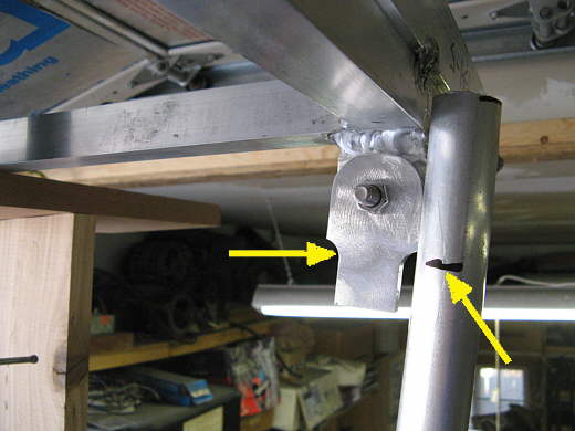
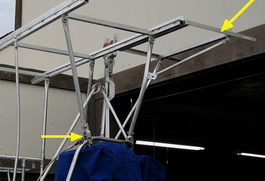
Next work started on the supports that would hold the frame up in the air. The top two arrows point to the method of putting uprights into the existing pushpit uprights that I had made when I opened up the back of it. The bottom arrow points to a bracket the will go on...
.......
...the front of the pushpit (see right arrow). The left arrow points to the uprights attach points at the back of the pushpit on the starboard side. The bottom arrow points to the support for the BBQ.
.......
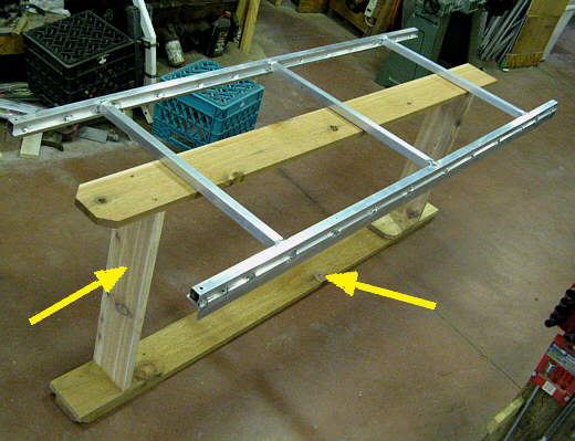
A wood platform was made to support the frame the right distance above the pushpit. The height was determined by the height of my shop door and also high enough so that we could board and leave the boat without having to crawl off.
.......
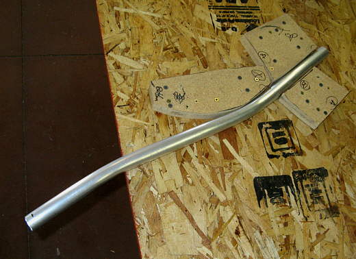
Here one of the uprights is being bent using the same method I'd used earlier on the pushpit.
.......
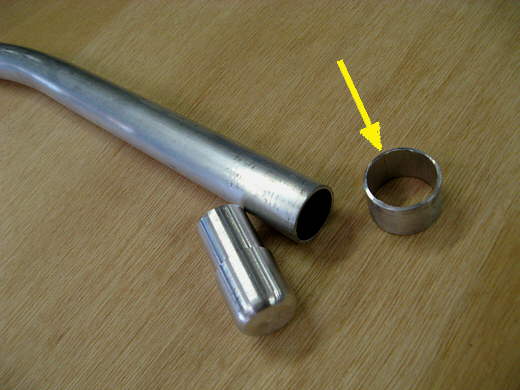
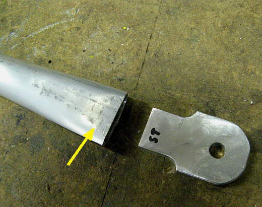
The arrow points to a bushing that keeps the upright from going down into the tube that will support it.
.......
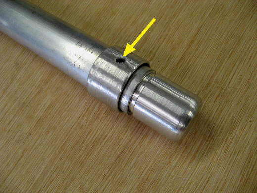
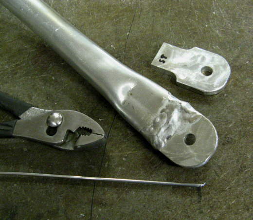
Here the pieces are about to be welded together. The hole is for a plug weld.
.......
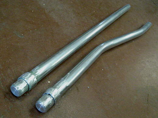
The two right side uprights....
.......
.....shown installed (arrows). Notice that they aren't attached at the top at this point. I wanted to make all of this easy and quick to remove so that I could put the boat in the other bay of the shop that doesn't have a high door. You can also see the platform that is holding things in place.
.......
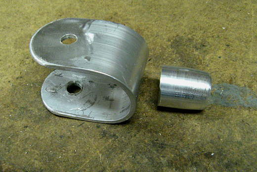
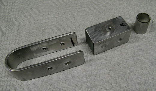
Another bracket being made and ......
.......
.....welded together.
.......
Tabs to go on the .......
.......
....... upper frame that.....
.......
.... the uprights will mount to.
.......
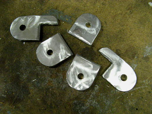
Tabs to use in making the.....
.......
.....uprights.
.......
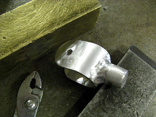
With a support tab bolted to an upright tab the upright was put into place at the bottom and marked at the top where it needed to be cut.
.......
Then the end was flattened with a hammer leaving an opening for the tab which.....
.......
......... was then welded on.
.......
Another bottom support for uprights on the port side.
.......
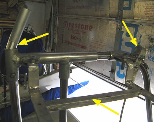
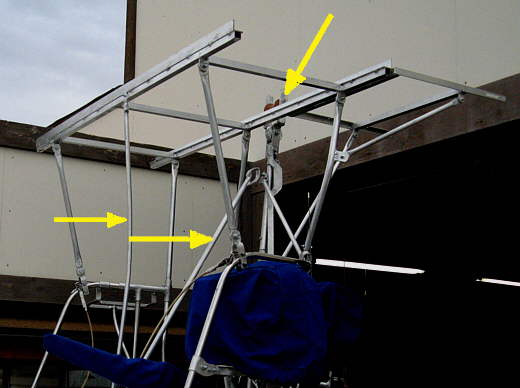
The top right arrows point to parts of the old 40 watt frame work that was moved up and attached to the new framework. New diagonal supports had to either be made or modified. The bottom arrow shows how the forward uprights were attached to the pushpit railing.
.......
The two arrows here point to two supports that are only used while the boat is on the trailer and on the road. I worried about air getting under the panels and maybe bending things, so added the support show with the left arrow. Its purpose is not to hold the framework and panels up, but to keep them down going down the road. The right arrow points to the support for the mast crutch/roller that is also only used when the mast is down and the boat is being trailered.
.......
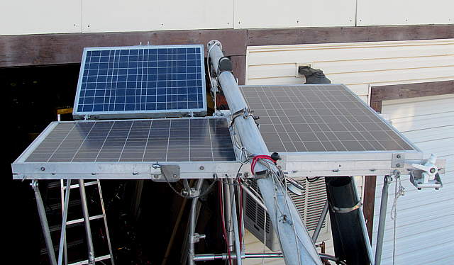
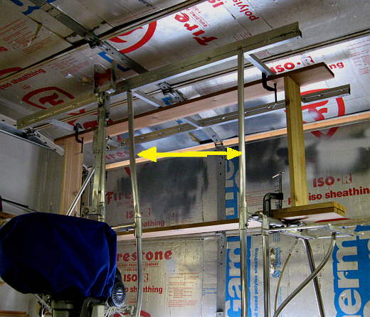
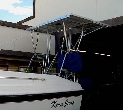
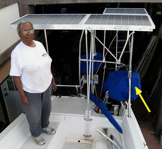
Here is an overall view. Not the prettiest thing, but on long trips we will enjoy the electricity that it will generate.
.......
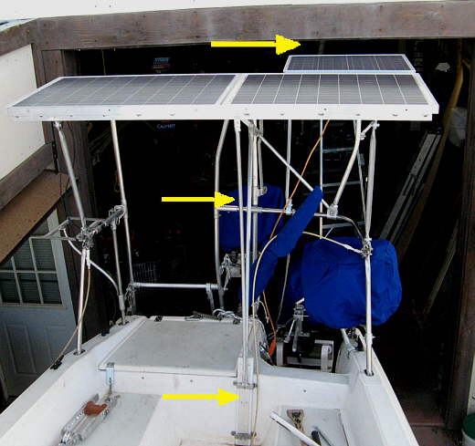
A view looking down and you can see the clearance on the garage door (couple inches). The bottom arrow points to the bottoms of the two supports that are removed on the water.
.......
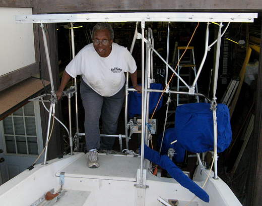
The panels are high enough what we don't have to crawl onto the back of the boat. Ruth is.....
.......
...... 5-2 to give you an idea of how high the panels are mounted. I'm 6-1, but still just ducking takes care of coming aboard. The panels are also high enough that I can still pull start the gen-set (right arrow)
.......
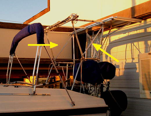
I added diagonal supports on both sides where the arrows are. Now the whole framework is really braced and strong and I probably could do away with the temporary center support I made, but it just takes a second to install and remove, so I'll use it for insurance. In the picture above and the next one you can see how it will look on the water without the braces used while on the trailer that are in the middle.
.......
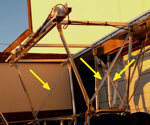
It looks somewhat cleaner with out the temp bracing in place. The side diagonals (2 left arrows) and the back diagonal (right arrow) really make the whole framework very ridged.
.......
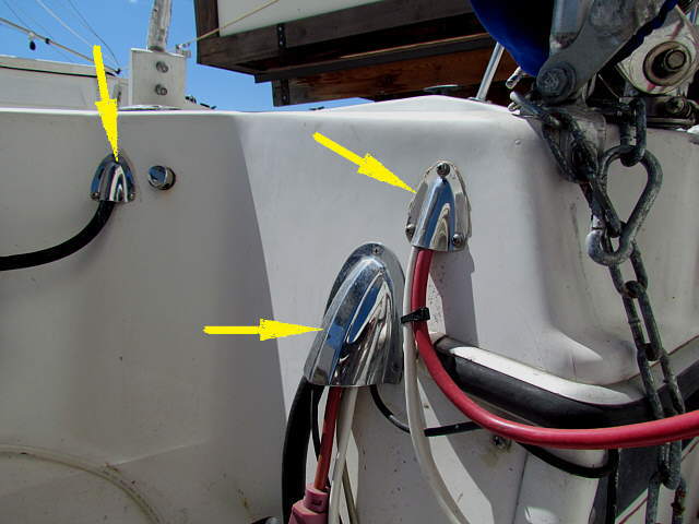
The wiring from the solar panels enters the laz via a clam shell vent, upper right arrow. The middle arrow points to where an extension cord, only used at home on a GFI shop outlet, the outboards electrical and the depth finder transducer wiring enter the laz. The top left arrow points to the smaller clam shell vent used for the fuel line from the inboard tank leaves the laz to the outboard.
.......
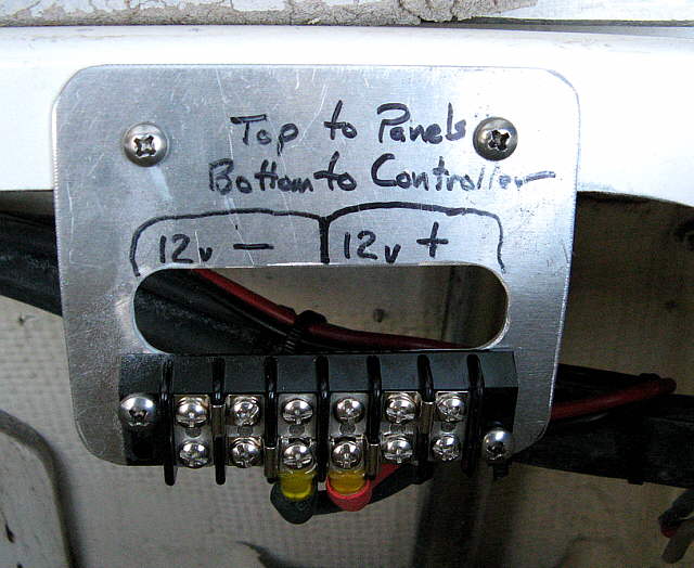
The wires from each individual panel connects at the top of this terminal strip. They are not installed above, but the 3 negative wires (3 panels) attach to the 3 left terminals and the 3 positive to the 3 right terminals. Also note the jumpers that then make all of the neg./pos. connections 'common'. Below you then see the one set of neg./pos. cables that go forward to the charge controller. All of the wiring from the panels to the terminal strip and from the strip to the controller are sized for less than a 3% voltage drop. Use a calculator like ( THIS ONE ) and make sure if you are using 'round distance' or 'one-way' to figure the 3% drop.
.......
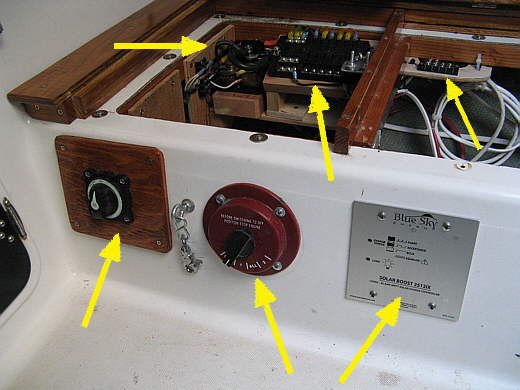
The wiring from the terminal strip goes to the Blue Sky MPPT Solar Boost 2512iX 25A,12V 3 Stage Charge Controller. We used the more expensive MPPT controller and the right size wire to take full advantage of the solar panels as there is only so much space on the boat for them.
This system has been extremely reliable and very efficient. We have more room on the Endeavour and are installing six 80 watt panels for a 480 watt total and hope to be almost completely energy self-sufficient with that configuration.