...............................--- Mounting Solar Panels At The Boat ---
...........................................................................................--- Part III ---
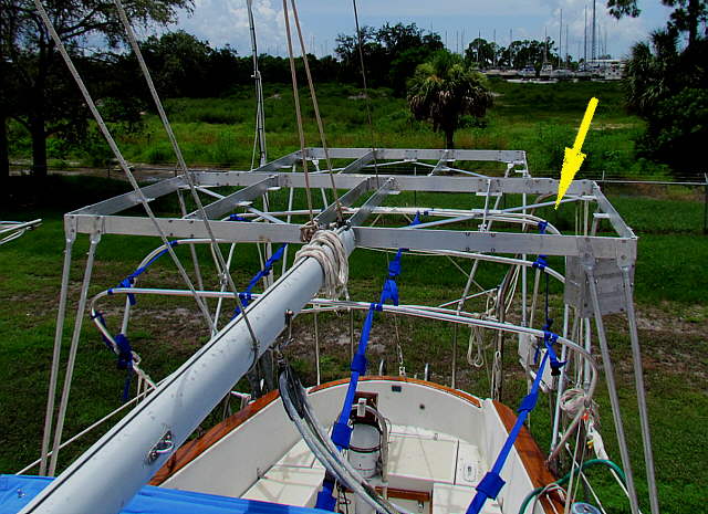
Now we will move on to the side and rear uprights.
..............
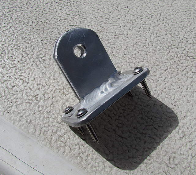
One of the double shear brackets made ( HERE ) was chosen for the bottom bracket for the side uprights.
..............
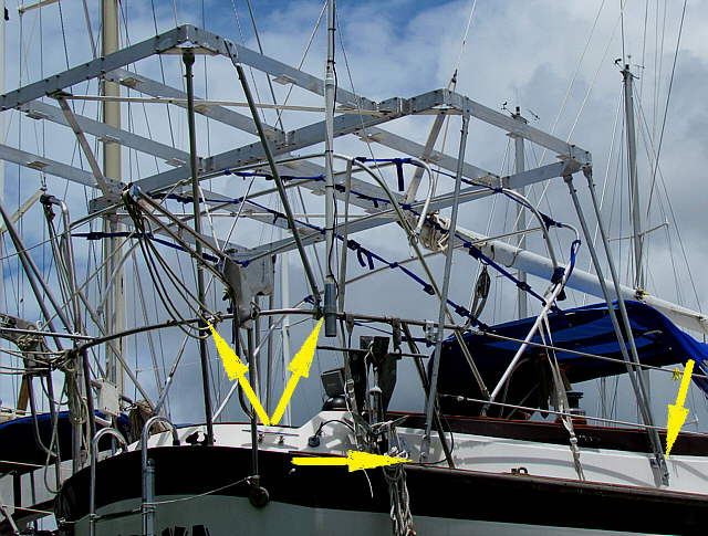
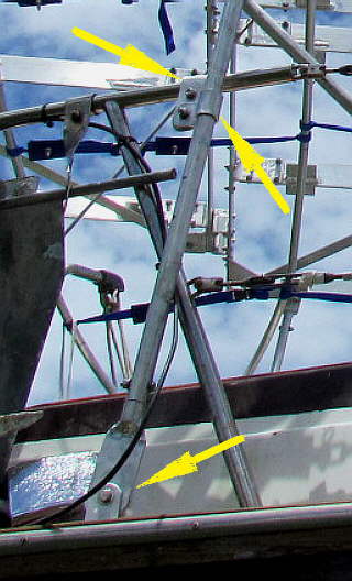
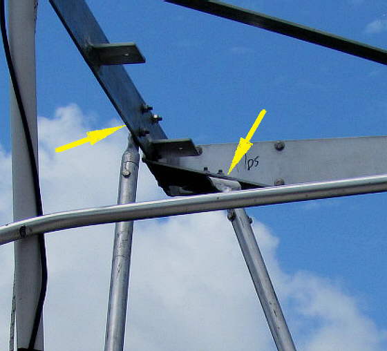
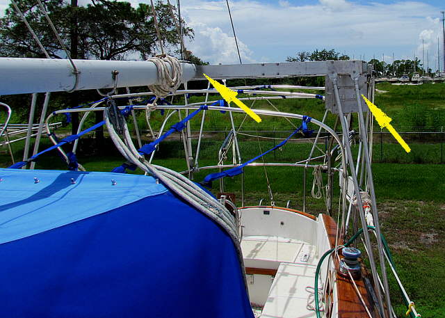
It was used where the bottom middle single arrow is above. You can also see the front coaming side mount, right arrow, previously installed along with where the back corner uprights attach to the pushpit railing, double arrows.
............................
The side upright is at the back corner of the front part of the frame where the 4 panels or located. The bottom arrow points to the double shear mount that was screwed into position with 4 SS screws. Above it the upright was also secured to the pushpit railing and the top arrow points to where it was attached to the frame.
The top and bottom brackets were the same ones used on the previous page and again were bent, drilled and cut to fit the location.
.....................................
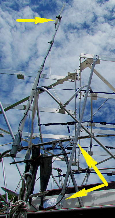
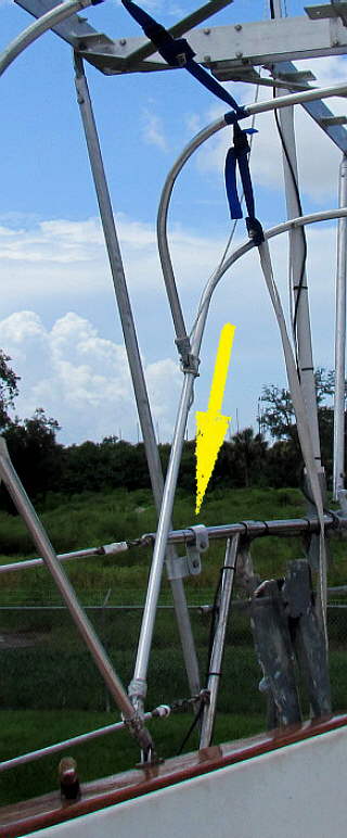
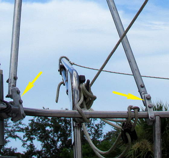
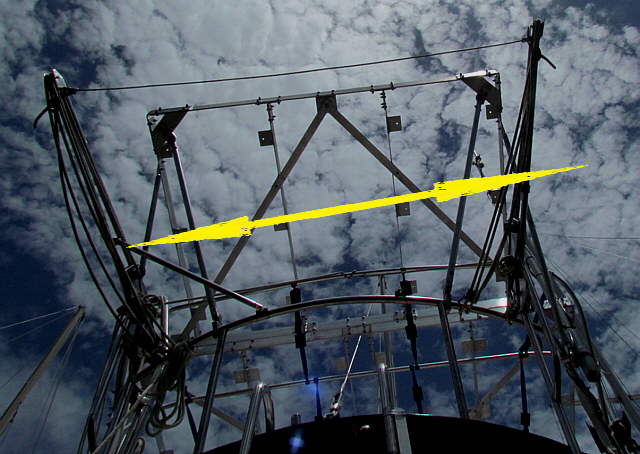
The top arrow points to the long distance WiFi radio (Bullet 2 HP) and Engenius Antenna. I'll be adding some triangulation to it with the new brackets and some tubing also. The lower arrows show the attach points for the side upright.
..............................................A little closer view of that area......
..............................................
... and another from inside the cockpit. Attaching to the pushpit helped to stiffen up the side support a lot.
......................
The link for the bracket on the upright is ( HERE ) and the link for the one on the pushpit is ( HERE ).
..............
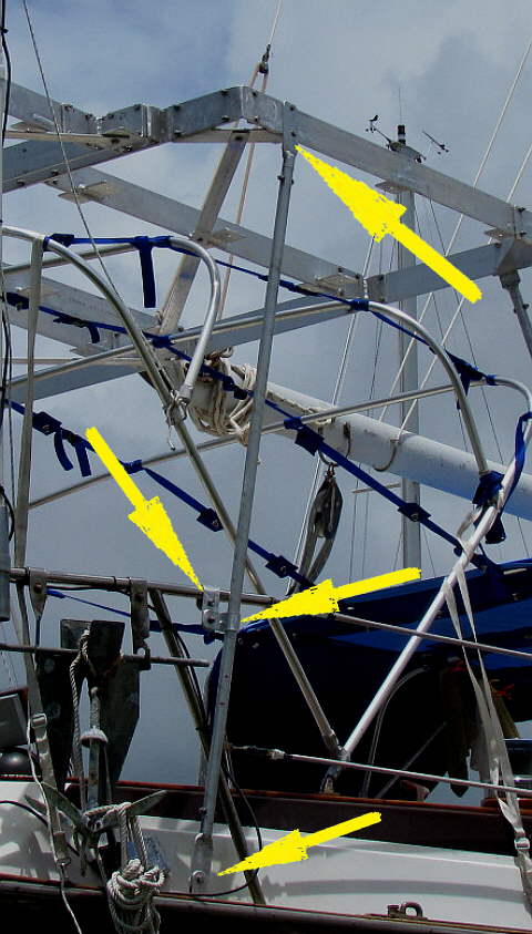
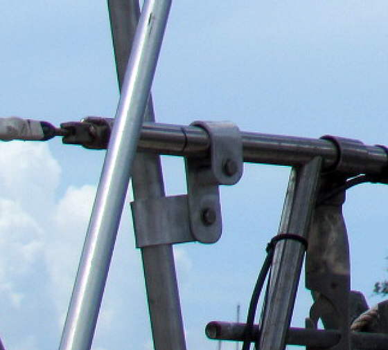
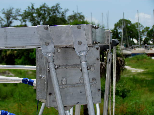
The two top arrows point to the brackets that I use for all of the top connections to the framework.
......................
One is on the side and the other to the bottom of a corner bracket, shown above.
......................
The bottoms of those uprights use the brackets made ( HERE ). The brackets on the pushpit rails were made ( HERE ).
..............
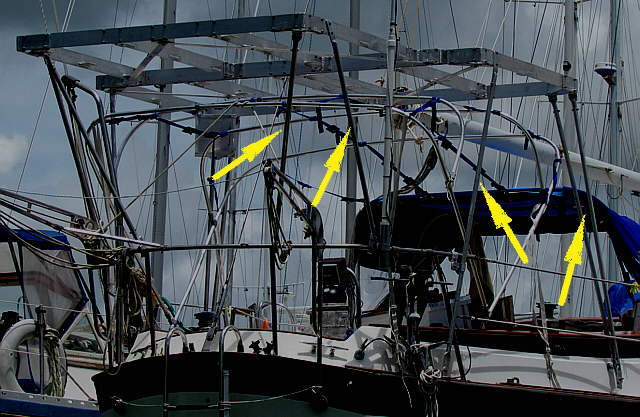
The back corner uprights stabilized the structure very well. Having all of the uprights angled at different angles helps the stability of the whole structure. There again I worried about that aspect at home, but I'm happy with the results.
All of the background rigging from other boats doesn't help in seeing what is going on. I'll try and take more pictures when the boat is on the water alone.
..............
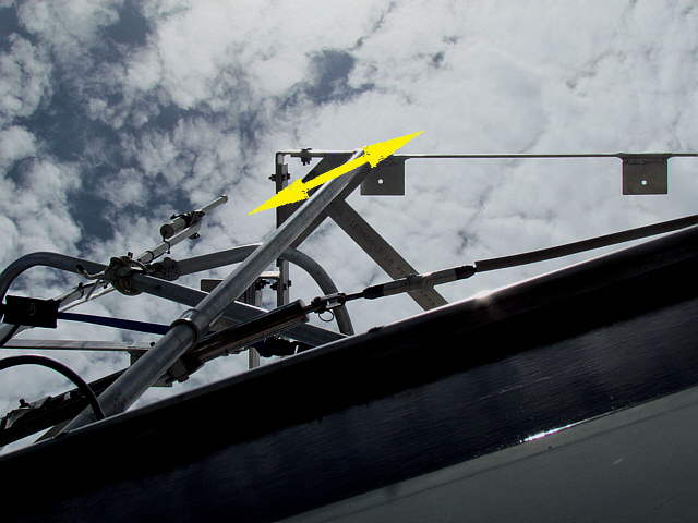
The only thing that I don't like about this install is the area of the frame that sticks out past the arrows above. About that much of the frame is out past a vertical plane above the rub rail at the bottom of the picture (the picture was not shot absolutely straight up). We ran our solar frame on the MacGregor into a piling more than once trying to leave a fuel dock at Marco Island and broke one panel. When we got that boat back home I repositioned the panels so that they didn't extend past the rub rails. We had never experienced pilings before our trip to Florida. I didn't want the same to happen with the Endeavour if I could help it.
To get all the solar up there that we wanted I did have to compromise this one area. I feel that the frame and supports are strong enough to take a slight brush on a piling going ahead where the piling would not catch a corner like what happened with the Mac. We are a lot more cautious now in docking and leaving docks and where this sticks out is quite a ways past mid-ship so I think we will be ok.
..............The rear frame with the two panels there hangs somewhat past the pushpit, the area back beyond the arrows, but it is quite narrow and not quite as bad as the davits and also the dinghy that will be stored there, so I don't anticipate problems back here. We will still be careful as the previous owner did smack the davits against a piling turning too sharply going away from a pier.
..............
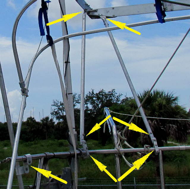
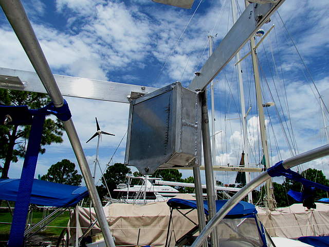
The middle arrow shows that there is a few inches clearance behind the rear of the boom to the frame. The right arrow points to the electrical junction box were all of the individual panel wiring will connect to the #4 wiring going down to the MPPT charge controller. The wiring down to the controller will exit the top of the box and then go down the upright there inside of a piece of conduit and through a fitting on the side of the coaming by the bracket there and the receptacle for the shore power.
..............
A close up of the box that was built ( HERE ) and .....
..............
... a view of the box from in the cockpit. All of the wiring will enter and exit the box on the top side of it. If you read the build of it you will have seen that any moisture that enters the top with the wiring will be diverted at the bottom out of the box.
..............
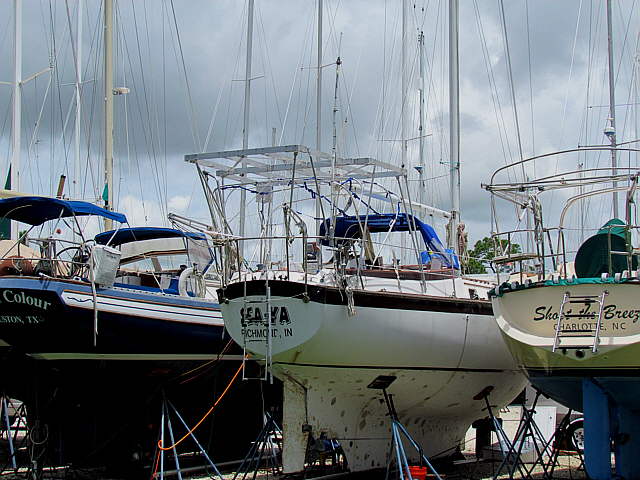
Above is a picture from a distance with the two boats near it for comparison. SEA-YA was the boats name, but it will be changed to Margaret Ann, my mom's first name and Ruth's middle name.
All the new canvas is in sunbrella Ocean Blue and to continue the theme the brown around the cockpit under the teak and the brown around the top of the hull will be painted in blue also along with the water line strip.
Below the strip you can see where the blisters were repaired after the boat was stripped down to the gelcoat. We have the barrier paint and bottom paint in storage and will apply it when we return in the spring of 2013. It will be barrier coated with Sea Hawk's Tuff Stuff (3 coats -- this paint goes on much thicker mil thickness wise that most other barrier paints and 2-3 coats is the recommended thickness.) Then it will receive 2 coats of black Sea Hawk Cukote Biocide Plus and then one coat of the dark blue Cukote Biocide Plus. It will receive more blue in the future when it wears through to the black. We used the same paint on the MacGregor with good results. This bottom paint is an ablative that will work going in and out of the water which will be the case with this boat as it will be up on stands in the yard when we aren't using her.
..............
Before we left the boat we installed one 80 watt panel where the arrow is. We ran it to the junction box and then from there we used an outside extension cord that I cut the ends off of down through a hatch cover I made to the charge controller. All wiring was disconnected in the boat with the exception of wiring from the controller to the start battery in the boat and to an automatic bilge pump in the bilge.
The house batteries, four 6 volt golf type batteries, on the boat were shot. Like the paint they will be replaced with new ones when we return to the boat.
So ends the solar install to this point. When I install the permanent wiring I'll update this with that info,
Sum