...........................................--- Solar Electrical Junction Box ---
..........................................................................................--- Part I ---
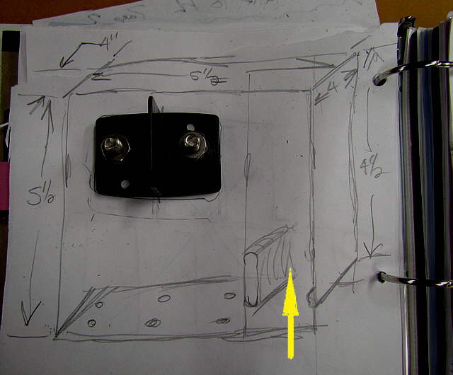
With 6 panels in the solar array a means was needed to run the wires from them to meet in a junction box of some sorts. From there two #6 wires would run down about 15 feet to the charge controller and then on to the four 6 volt batteries that make up the one house bank.
..............
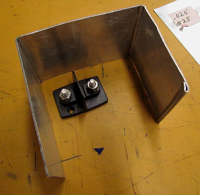
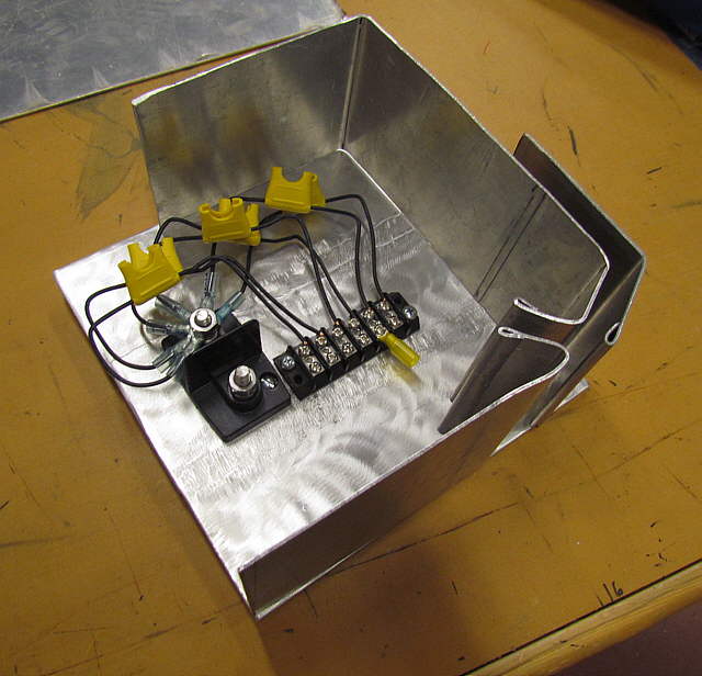
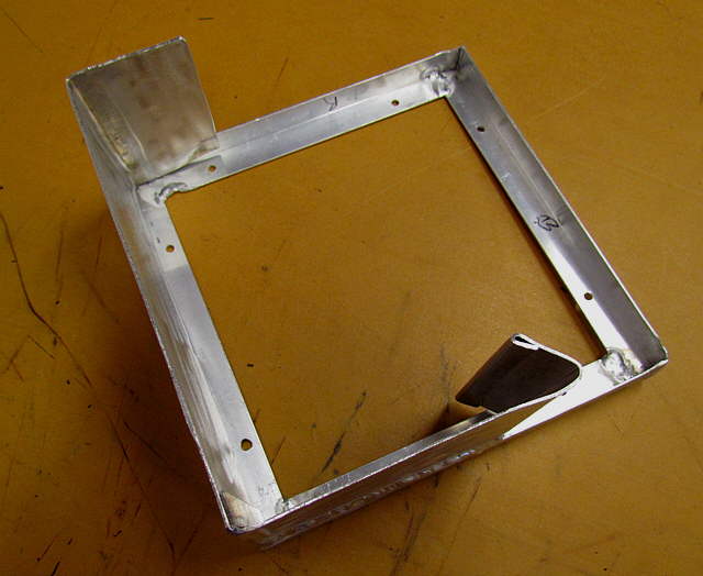
I planned on running the positive leads to one side of the dual power post above and the negative leads to the other side. I drew up a box with dimensions that I felt would work (it didn't). I'd planned on the wires coming up from below, arrow, into the box but would change that.
..............
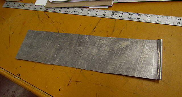
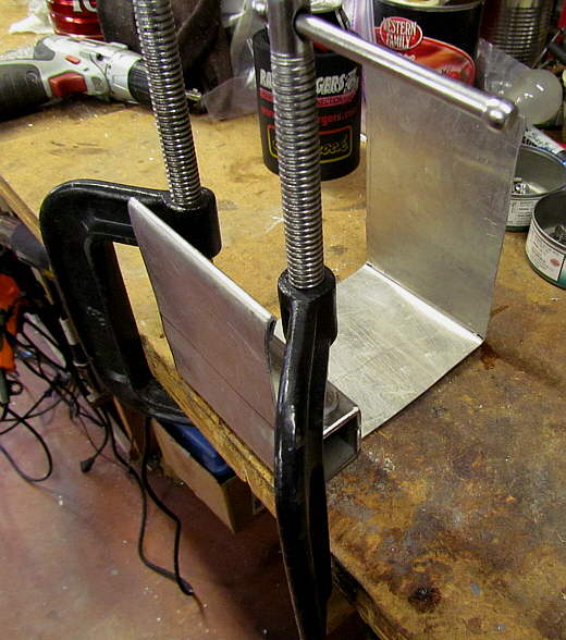
The piece of aluminum, above, was ...
......................
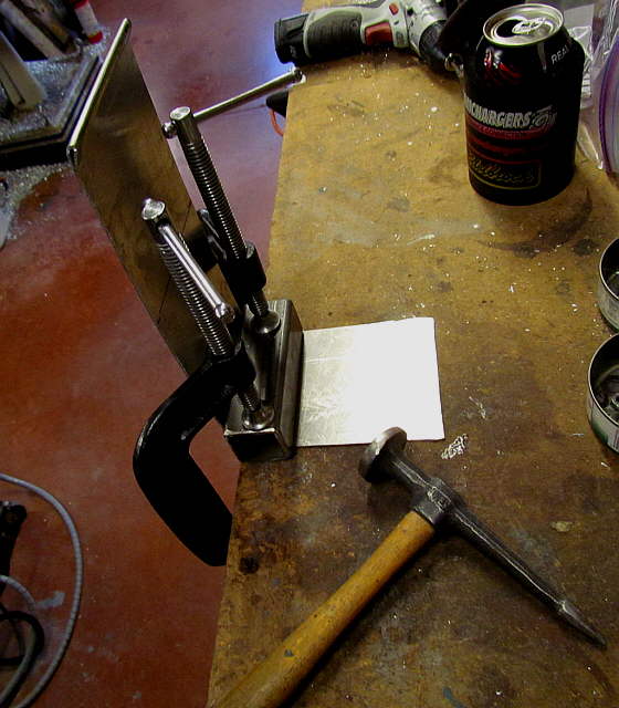
.... clamped to the workbench and I started to put 90 degree bends...
..............
...on it using the body hammer...
...........................
... and the simple clamp at the edge.
..............
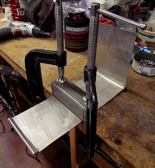
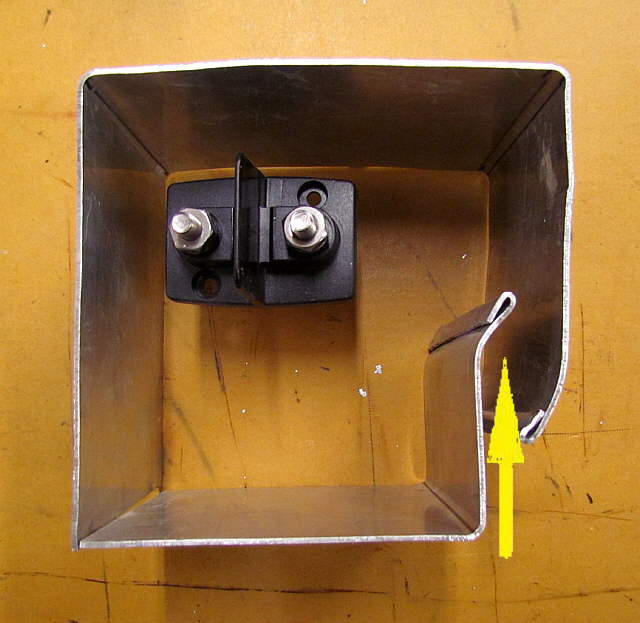
The lip at the right was suppose to keep the wires from chaffing on that edge. At this point I felt...
..............
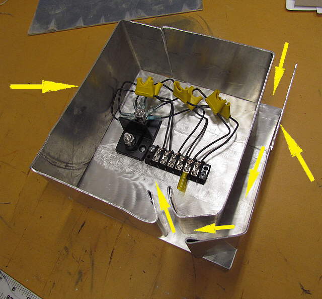
...that the box was going to be too small to get wires from 6 panels and also the main feeds down into the boat all in the box. The arrow points to the path I had in mind for the wires.
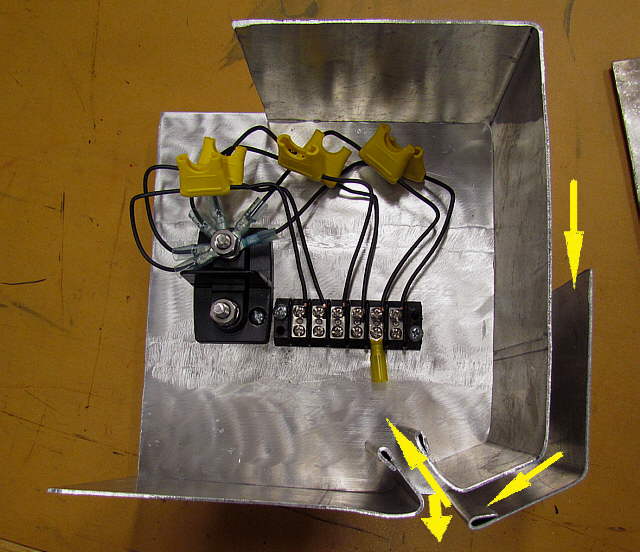
I decided to use what I had...
..............
...and add to it to make a larger box. I made the back and mounted the dual power post and a terminal strip where the panel positive wires would attach. Form there each circuit would go through a fuse holder and on to the positive main post that the main feeds would also attach to. The reason for the individual fuses is so that if a panel or wire to a panel shorted out that the current from the other 5 panels couldn't go down the wire towards the shorted panel.
The arrows show the new routing for the wiring. Instead of entering from the box bottom this route will be cleaner looking as all of the panel wires are up high under the panels and this box will be located on the port forward leg supporting the array. The wires will come down and make the bend up into the box. Any rain water that might reach this will follow the wires down, but exit via the bottom opening, very bottom arrow.
..............
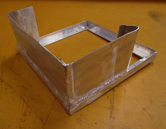
I cut the piece that I had first bent up and used the bends and ...
..............
.... then cut additional pieces to make the sides of the box.
..............
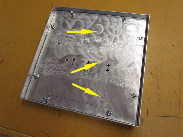
The back of the box is actually 3 pieces of 3/16 in strap welded....
..............
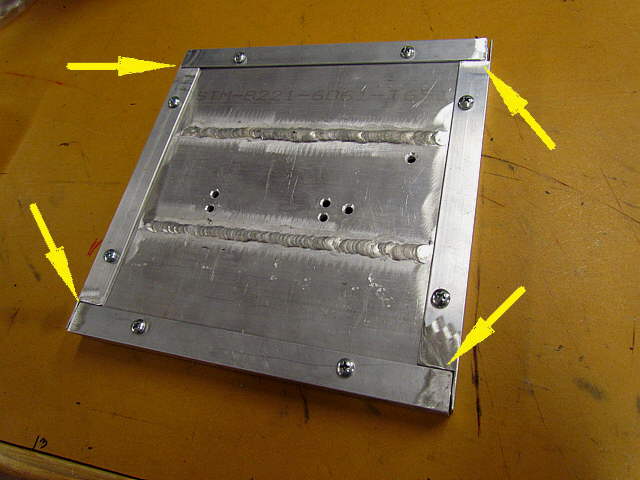
.... together to form one piece. I ground the welds down on the inside and should of on the outside also. Next pieces of angle were cut and screwed temporarily so that the corners could be welded. Then the back was unscrewed for now and ...
..............
.... the sides were welded to the angle framework piece....
..............
... by piece around the perimeter.