...............................--- Mounting Solar Panels At The Boat ---
.............................................................................................--- Part II ---
At this point we have the framework for the six 80 watt panels up on the temporary wooden mount. Time to attach uprights to it.
It took a while to come up with a location that I felt was good for the front uprights. The main concern was trying to make sure the sheets from the headsail would clear the upright on their journey to the winches. There is a track for a block for the sheets down on the side deck where the hull meets the deck. I used where the block was and how that line ran when we bought the boat to be pretty much the deciding factor. The previous owner had owned the boat for a number of years and I was hoping they he pretty much had the block/line in the best location for the headsail. Saying that the uprights are such that there is still room for considerable adjustment for where the block is on the track with out the line contacting the uprights.
..............
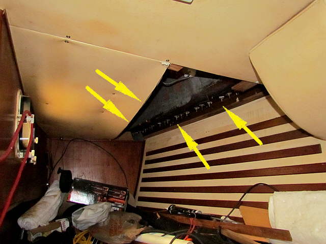
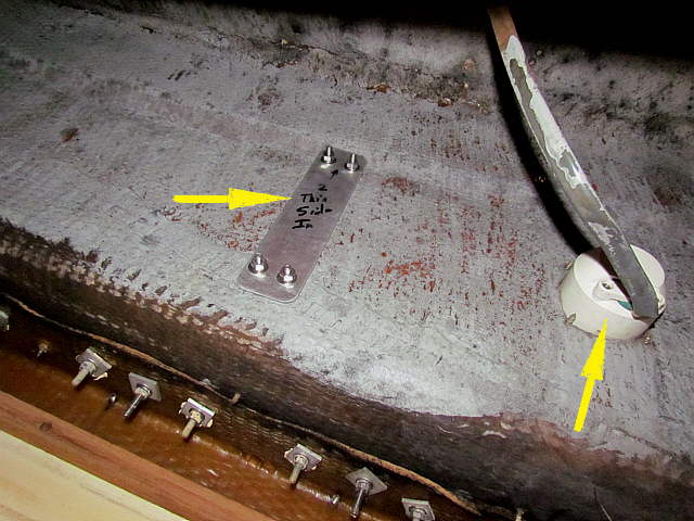
To mount the bottom bracket for the forward uprights I did a little surgery to the cabin top above the quarter berth just behind the nav. station. First I took a sharp knife and cut the headliner length wise where the two left arrows are. Then I cut the plywood above the headliner along the same line and dropped it out. This will help in future access to this area, making it simpler and faster to access the area.
The right arrows point to the hull/deck joint in this area.
..............
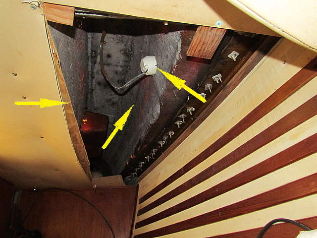
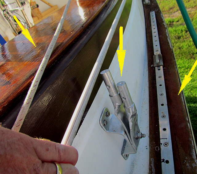
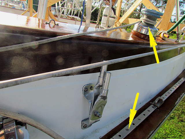
The coaming is quite high on these boats and I planned to mount the bracket on the outside of the coaming about where the middle arrow is. The right arrow points to the receptacle for the shore power.
The left points to the cut I made in the headliner and plywood above it. When I finished I screwed a length of plywood above and along the cut area in such a way that it overlapped the cut. Then I replaced the panel that was taken out and screwed it to the plywood and to its previous mounts by the hull. Then I pushed the headliner material into place and used one of the long pieces of trim that were left over from the V-berth remodel to cover the long joint. It looks fine and now it is easy to access the area.
On the starboard side this wasn't necessary as this boat has the plan where there is no quarter berth on that side. You gain access to the inside of the coaming by climbing down into the cockpit locker under the seat on that side. One thing I like about this boat is that most areas are accessible pretty easily.
We had looked for an A plan Endeavour with the quarter berth on both sides, but after having the boat we are very happy with the layout of everything on the B plan and like the access to things that it affords.
..............
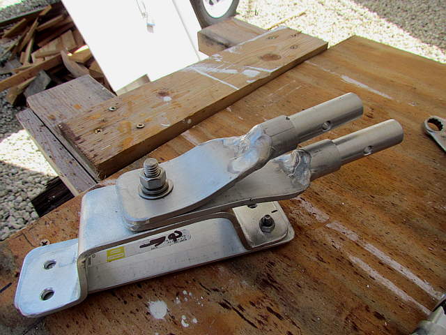
Two brackets like above were bent up in the vise I had brought to use on the outside of the coaming for the forward uprights.
......................
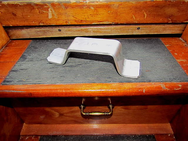
Above are the pieces that make up the outside mount at the bottom of the upright, actually 2 uprights go up to the panel frame from this location. The arrow points to the backing piece that will go on the inside of the coaming.
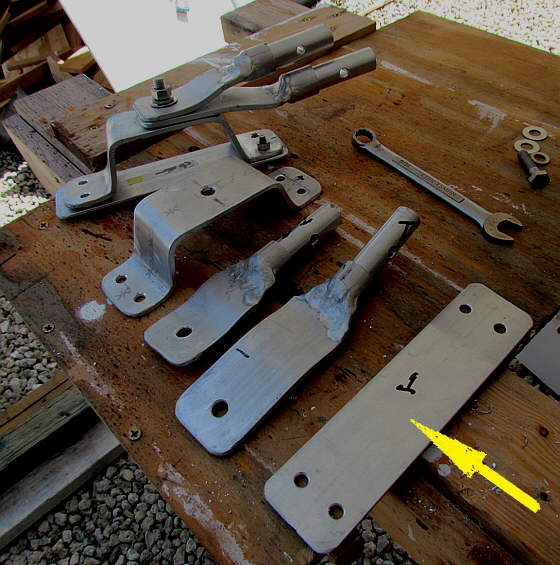
The next two pieces are two of the ones that were made ( HERE ) and you can see they have been modified in length and the corners rounded off and they have also been bent to work in this location.
..............
A close-up of the pieces to be used on one side. Again the bottom piece will go inside of the coaming.
..............
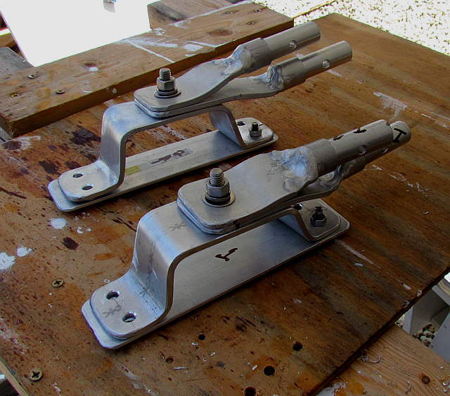
The mounts for the port and starboard sides are mirror images of each other.
..............
Ruth held the brackets on the outside and inserted the SS bolts and I put the backing plate on from the inside and tightened things down. To bed this hardware we used butyl tape that we had bought from Maine Sail, who is on a number of sites. I think it will do a good job in this application.
Again the right arrow points to the receptacle for the shore power and all of the bolts and screw ends you see at the bottom are for the joint where the deck is attached to the hull.
..............
The middle arrow obviously points to the newly installed mount for 2 upright tubes. The left points to the the coaming top that Ruth had refinished about a month earlier and the right points to woodwork that hasn't been refinished and to the track for the block that is used with the Genoa sheet on this side.
..............
The location for the mount was based on the geometry of how the sheet ran from the block down on the track, bottom arrow, to the winch up on the coaming. I think I have the mount in a location that will work, but time will tell.
I'd also considered putting the mount, a different one, up on the coaming or down next to the track, bottom arrow, but felt those positions provided more problems than they solved. All of the other mounts don't have the issues that this one did.
...............................
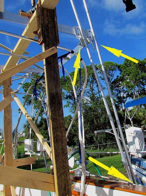
The bottom right arrow points to the area where the new mount is just below the coaming top and you can see the two pieces of 1 inch tubing coming up from the mount that at this point aren't attached to ....
..............
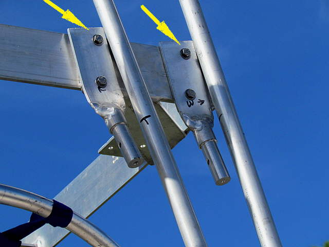
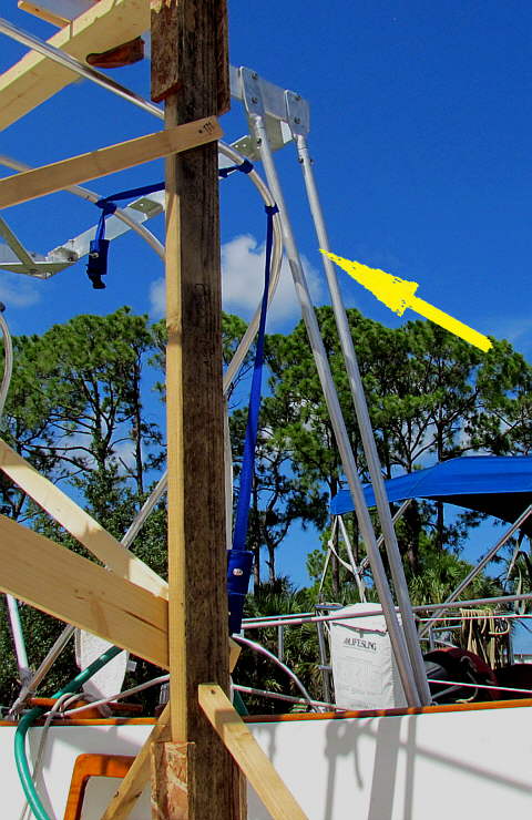
... the frame. Here is a close-up of the tubing coming up and the pieces they will attach to. The brackets have been drilled, bent and mounted to the frame and were then marked on the top backsides with a marking pen. Then were....
..............
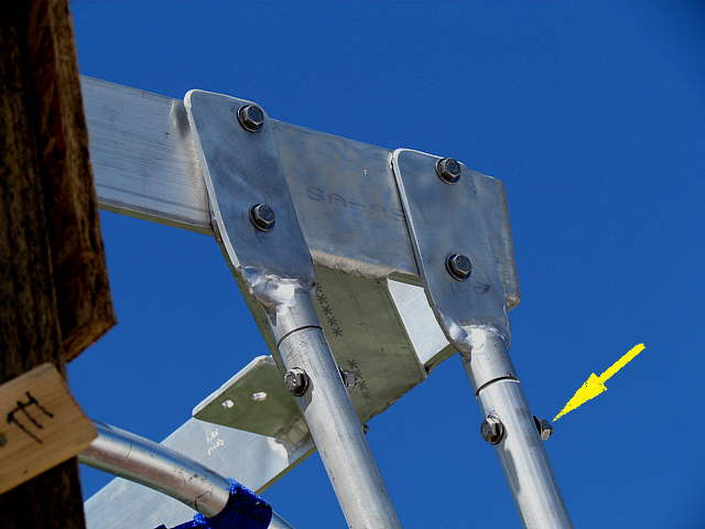
.... removed and the tops cut and corners rounded so that they were flush with the tops of the frame. You can see by leaving the flat strap parts of these brackets long at home they could be modified at the boat. The tubing was drilled and bolts were used to hold the tubing to the bracket. The new brackets worked very well up to this point and the bracket to tube connection also seems to be working well.
...............................The two uprights here give some triangulation to this area and help to stop side to side movement of the frame above. I worried a lot about that, but I'm happy with the results.
..............
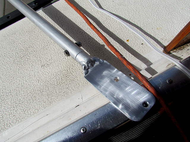
Another picture of the bracket that was made ( HERE ).
..............
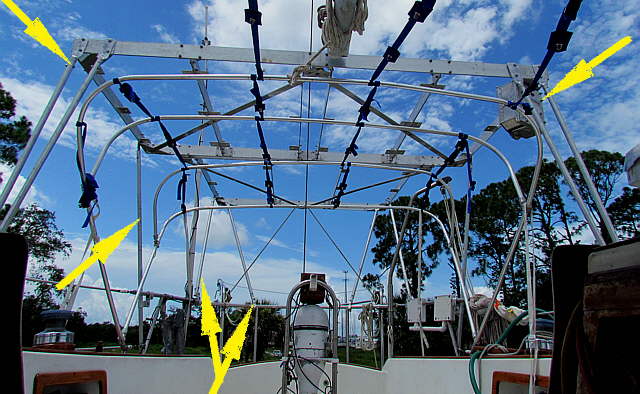
Above the two top arrows point the the front uprights and the electrical junction box (top right arrow). The double bottom two double arrows point to the two back/corner uprights and the middle left arrow points to a side upright. More on all of those on the next pages.