...Return To Mine & Other Bonneville Car Construction Pages
.Previous Page...............B'ville Car Index Page.........................Next Page
.................Steering Bellcrank Part III & Tie Rods
................... .
.
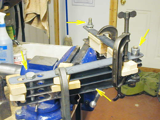
Back on ( page 54 ) and ( page 55 ) I made the first bellcrank to connect the steering box to the tie rods. Here I'll quickly show how I used the first one to make a duplicate one. I made all of the pieces back when I made the first one. Here I have placed the first one into a vice and and used pieces of wood that are the right thickness to clamp the pieces that make up the second one to the first one.
................. .
.
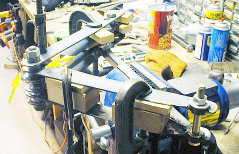
I used three bolts to locate the two ends and the pivot point. Next I tack welded the arms to the center bushing (left two arrows) and the bushing at the end of the arm on the right above.
....................... ....................
Here you can see the two bellcranks still bolted together.
......................... .
.
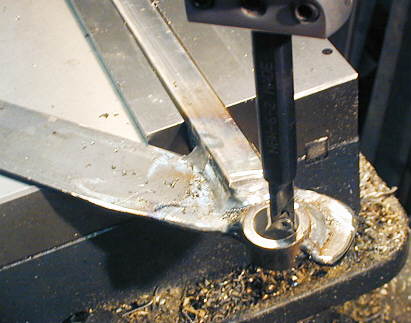
I bored the end that attaches to the rack and pinion out to accept a bushing.....
........................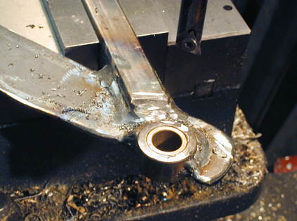
.....seen inserted here.
.......................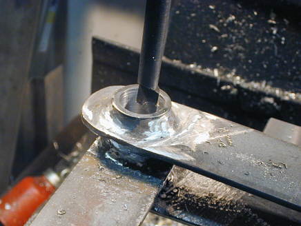
Next the center pivot was bored out to accept two more............
..............................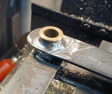
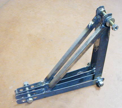
.............bushings. One on the top and one on the bottom. Finally I made a bracket that located these bell crank to the left side of the car similar to the one I constructed back on ( page 55 ).
...............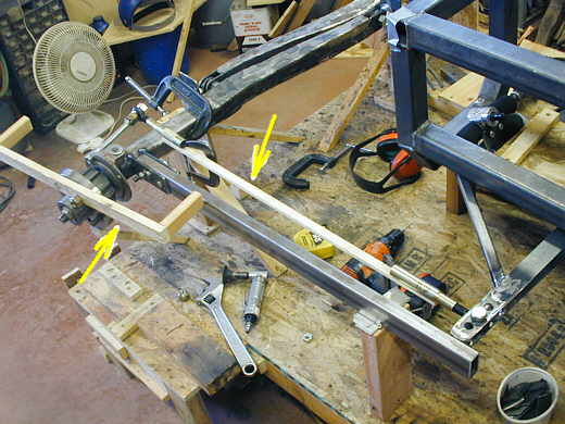
In the picture above you can see I was using a piece of wood to represent the tie rod going from the bellcrank to the steering arm on the front spindle ( note: the steering arm in the picture is not the final one. See page 59 for the finished steering arm). To make the tie rods I..........
...............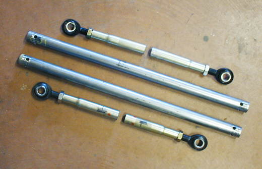
............... took two 3/4 inch Swedged Sleeves I got from Speedway motors and cut them in half (top and bottom of the picture). These had 3/4 LH and RH Pro 1 Heim Joints screwed into the ends of them. I measured two pieces of 1 inch DOM tubing the correct length and drilled 4 holes at 90 degrees to each other a little ways in from both ends. The holes will be used to plug weld the sleeves to the DOM.
.......................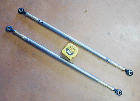
Here are the two tie rods with he sleeves slid in and tack welded for now. The sleeves were a perfect slide fit inside of the DOM.
..................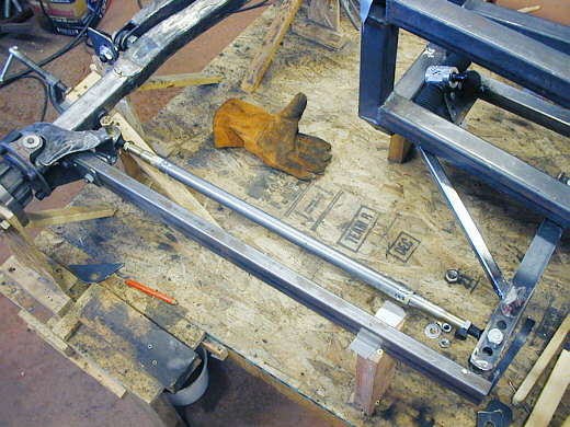
Here you can see the tie rod in place between the steering bellcrank and the
steering arm on the front spindle.
..................................................................Next
Page