...Return To Mine & Other Bonneville Car Construction Pages
.Previous Page...............B'ville Car Index Page.........................Next Page
....................................... Steering Bellcrank Part I
..................... .
.
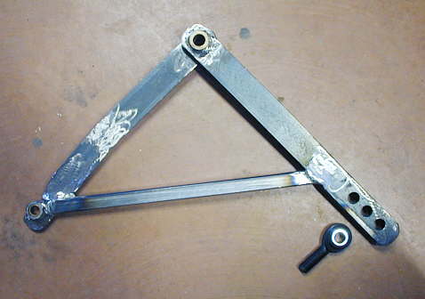
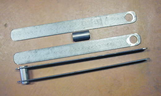
I'm going to start this page off by showing the finished product so that the pieces I'm making below make more sense. This is a bellcrank for part of my steering linkage. The left side will attach directly to the rack and pinion box on the previous pages and the right end will attach to a tie rod going to the spindle. There will be one of these for each side of the car. So lets begin.
............... .
.
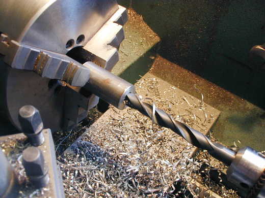
I needed to make four bosses to put bushings in. Two for the end of the arm that attaches to the rack and two for the pivot point of the bellcrank. I used 1 inch dia. cold rolled steel stock and drilled the center undersize for the bushings.
........................... ....................
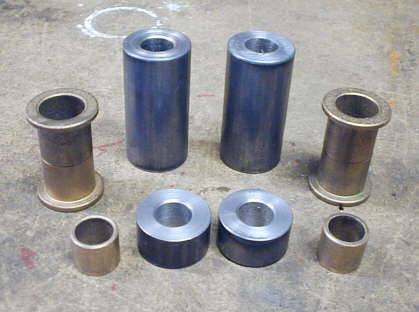
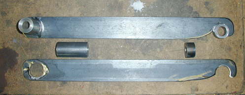
Here are the four bosses with the bushings that will go in them. I needed to weld the bushings to the bellcrank first and then bore them to the final size after the welding was completed to avoid distortion. The short ones are for the end of the bellcrank where it attaches to the rack and the long ones are for the pivot.
............................ .
.
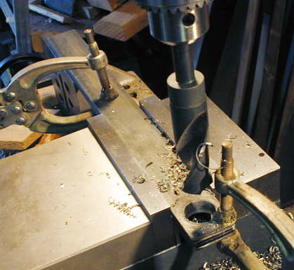
Here I am drilling four pieces that will be used to make the leg of the bellcrank from the pivot out to the heim joint for the tie rod. The hole is 1 inch diameter for the boss that will form the pivot of the bellcrank.
.................
Here are the four pieces showing how they will be welded to the pivot point.
....................
I then made two pieces for the other arm of the bellcrank. The large hole on the left is the pivot end and the cutout to the right is for the small boss/bushing where it attaches to the rack and pinion. That end was also shaped for clearance issues.
.......................................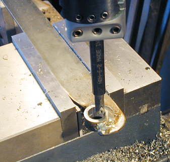
Here I have welded the boss to the rack end and I'm boring it out to the final size for a tight fit on the bushing.
............................ .
.
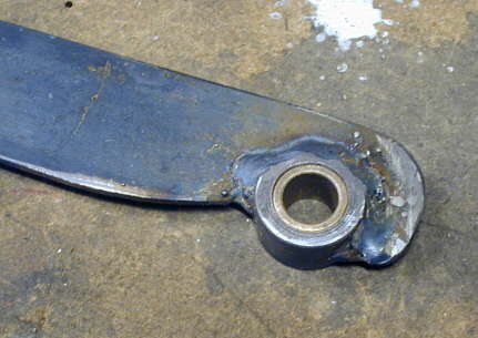
Here it is finished with the bushing installed.
................. .
.
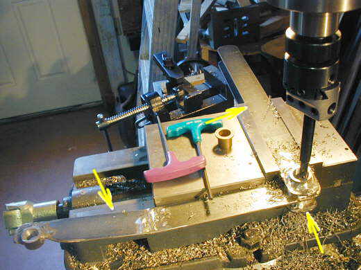
Next I welded the arm of the bellcrank that goes to the rack (left arrow) in the middle of the pivot bushing (bottom right arrow). Then at a 90 deg. angle I welded the two pieces that make up the other leg of the bellcrank (top-right arrow) to the pivot boss above and below the other arm (bottom right arrow). After the welding I put the bellcrank in the mill vise and bored the boss out for the two bushings that go into it.
................. .
.
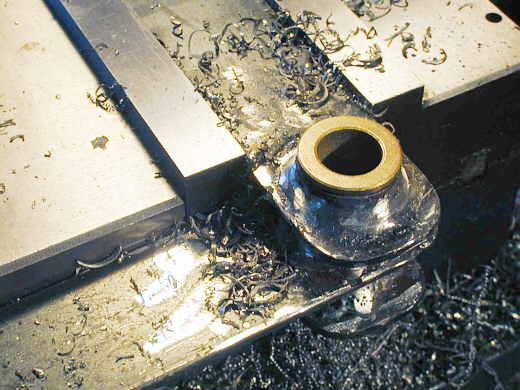
A view of the bushing installed.
.............................. .
.
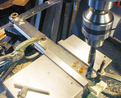
Next I drilled 3 holes at the end of the bellcrank where the heim joint for the tie rod will connect. The center hole will give a 1:1 ratio for the bellcrank. Using the inner hole for the heim will result in slowing the steering down by 8% and if I was to use the outer hole the steering rate would go up 8%. The rack I got is suppose to be slow for B'ville type cars and the rest of this I'm guessing at.
.........................
Finally I triangulated the bellcrank with a piece of 3/4 inch thin wall square tubing. Also shown is the 5/8 inch heim I'll be using that will be attached to the end of the tie rod.
................... .
.
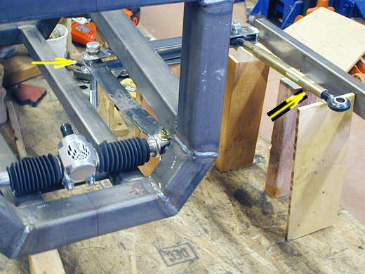
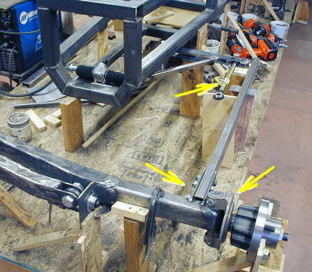
Here is the bellcrank blocked into position. The end of the one arm is attached to the end of the rack & pinion. The left arrow points to the pivot point. I'll make a bracket to attach it to the frame in double shear. The right arrow points to a piece that represents the tie rod. It will be longer and go up to the steering arm on the spindle.
............................. .
.
Another view showing the left spindle (right arrow). I'll make a steering arm 6 inches long that will attach to the spindle and will go out past the radius arm to about where the bottom left arrow is. The tie rod (top right arrow) will be much longer and attach to the steering arm where the bottom left arrow is.
.................... .
.
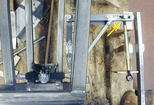
You can see the three holes (arrow) that will allow the steering speed to be slowed down a little or speeded up a little. The radius arm just to the right of that area will be shortened some and a bracket attached like on the front axles for a heim joint. The joint will be located just opposite the end of the bellcrank. Since the tie rod and the radius arm will be rotating about almost the same point, hopefully there won't be much bump steer. Tom suggested attaching steering dampeners. I think that is a good idea and will follow through with it.
I also plan on adding two guides for the bellcrank. One above and one below about where the diagonal piece hits the back arm to the left of the holes for the heim joint. They will have nylon or aluminum pads on them for the bellcrank to slide on and will help to stabilize that leg.
On the menu next is the steering arm and tie rod and then the other side and
on to the front suspension. I'm already starting to wonder if one more year will see this car finished to the point
where it can make the 2007 Speed Week. There is a lot to do.
..................................................................Next Page