...Return To Mine & Other Bonneville Car Construction Pages
.Previous Page...............B'ville Car Index Page.........................Next Page
............................................. Steering Arm Part II
On the last page we left off with the first steering arm finished and ready to start on the second. The problem I was faced with was making a duplicate that would be a mirror image of the first.
........................ .
.
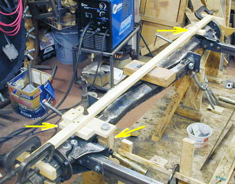
I started by making sure my two front hubs were parallel to each other (no toe in or out). Then I clamped some 1 X 2's to them in the same place and level. Next I ran a 1 X 2 across the front with one edge of it just above the center of the king pin on both spindles. Then I drilled a 5/8 hole in a piece of particle board (between two lower arrows) and put a 5/8 bolt through the hole and down thru the steering arm where it attaches to the tie rod. I squared the particle board to the cross 1 X 2 and placed a marker/stop (left arrow). Then I measured from the hub to the marker piece and put another marker piece on the other end of the 1 X 2 the same distance from the right hub (top right arrow).
................... .
.
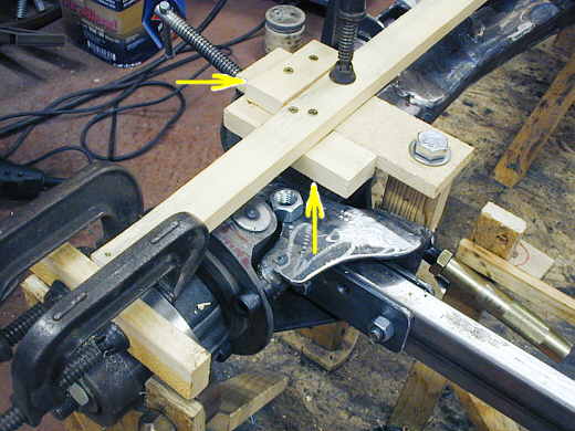
I then added another stop/marker (top left arrow) to the back of the particle board with the bolt thru it. I cut a piece of 2 X 2 to fill the distance under the particle board down to the tie-rod attach tabs with a hole in it for the 5/8 inch bolt.
................... ....................
I then attached the particle board and 2 X 2 spacer to two tabs and the end of the right tie-rod and placed all of this on the right side of the 1 X 2 against the stop over there. So now in theory, that I checked by also measuring, I had the tabs for the tie-rod hanging where they should be in relation to the spindle.
................... .
.
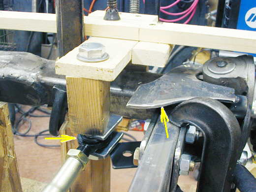
I made a second jig out of a 2 X 4 and a piece of plywood (bottom of picture) and first placed it on the left side of the car to get an angle for the tabs over there. Then I placed the jig on the right side of the car (above) and transferred the angle to the tabs for the tie-rod on this side. Now the tabs were not only located in the right place they were at the same angle as the other side of the car.
...................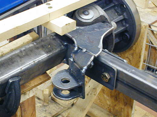
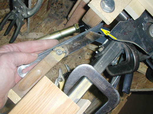
Then I started making pieces to weld the tabs to the pieces attached to the spindle. Here the tabs are connected to an upright that is attached to an angled piece that is attached to the top of the steering arm. Yet to be welded into position is the horizontal bottom piece of the steering arm that goes under the radius arm. I then removed the piece and finished welding it together like I had done on the other side of the car (last page).
...................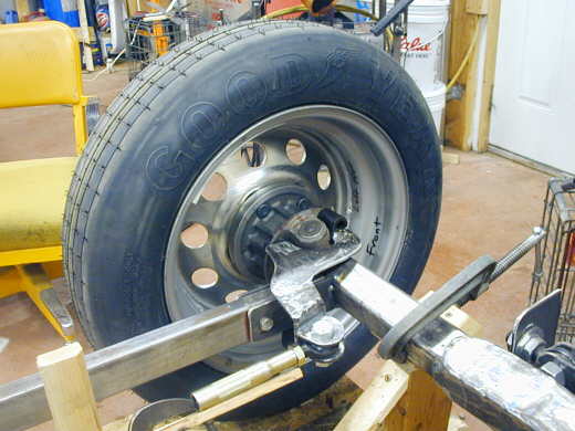
If you followed all of this I'll give you an "A". Here is a picture of the left side with the wheel/tire mounted so I could see if it would all work. I just had the temp wood tie-rod and turned the steering box with my fingers and everything seemed in order.
..................................................................Next Page