................................................Return to Sumner's Home Page
.......Return To Mine & Other Bonneville Car Construction Pages
.............................................Return to Hooley's Index Page
.. .......................Previous Page ............................................................................. ....Next Page
......................................The Stude's 2005 Changes.- Page 4.
This year with the one piece front on the Stude we can't tow it to the starting line and back to the pits. We also wanted to maybe push it off the line to help save the clutch/transmission and not load the motor so much. This necessitated building a push plate for the front of my truck. Here is the main part of it, which I will call the "cage".
............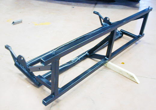
This went pretty fast and just took a couple part days. Since I don't have a front bumper this was a little tricky. I had two mounts under the front of the truck where I once put a tow bar to pull the truck when it was under construction. I tied into those mounts with the ears that have the 5/8 inch holes in them. I welded two short pieces of 1 inch square tubing to the bottom of the frame rails on the truck. The small pieces of 3/4 inch tubing that stick up behind those ears go up into them and guides this whole piece in place (like a receiver type hitch) and they hold the cage from falling down. Once there is force on the front plate (while pushing) all of the force is take with the 5/8 inch bolts and the pieces that stick through the grill (see two pictures down).
............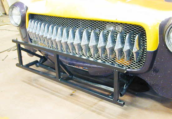
Here is the cage up in place. The very bottom two round pieces (can't see the back one here) with the ears on them are from the original tow bar I had made. I cut the rest of the tow bar off and scabbed the rest of this cage to what was left..
............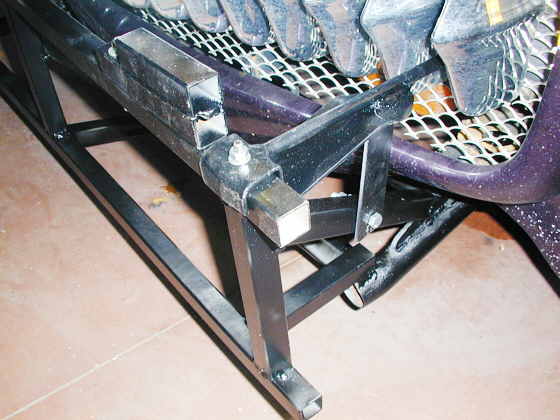
Here you can see the pieces on the top of the cage that go into the grill and butt up against the front of the frame rail area. They bolt on with two bolts. The one on the diagonal piece keeps them from wanting to move in the vertical direction and the web welded on the "U" shaped part that goes over the top of the cage helps to keep them from moving in the horizontal direction.
To the left of this piece on the cage is a spacer made out of two pieces of 1 inch square tubing welded together. It raises the push plate to the proper height. I can remove it to lower it all the way down or just use one 1 inch square tubing to lower it 1 inch. I wanted the push plate to be adjustable in height in case I needed that in the future.
............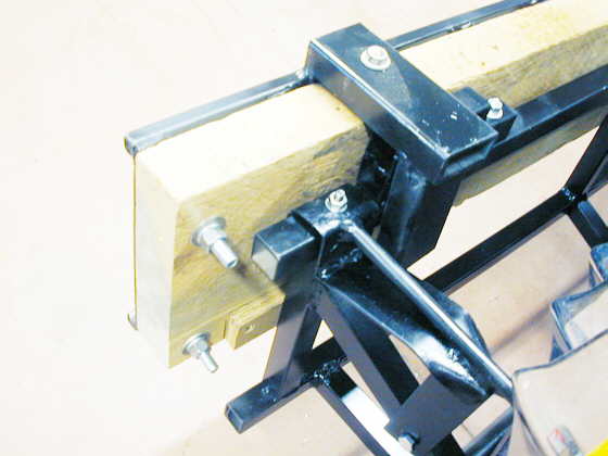
Another shot of that area showing the spacer piece more clearly. You can also see how the push plate hangs on the cage via the pieces of 1 1/2 rectangular tubing that are welded to it and slide over the cage. The small block of plywood at the bottom of the 2 X 8 pushes the push plate out so that it is 90 degrees to the ground. I can use different thickness of plywood or metal here to adjust the angle to the ground of the push plate.
............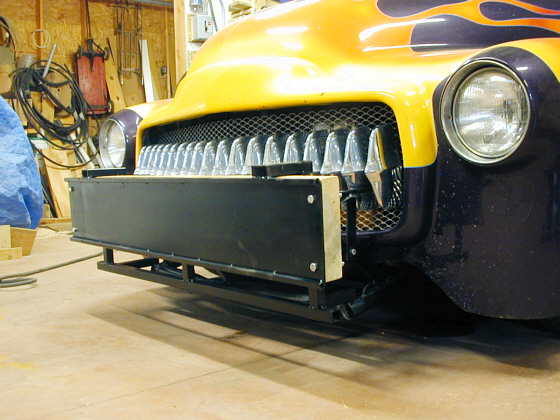
And the finished piece. It is faced with 1/8 inch plate so that the wheel on the push bar at the rear of the stude does not dig in like it could on just a wood surface.
.............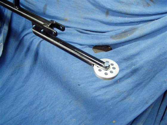
Here is a picture of the push bar that sticks out the back of the Stude. The parachute attaches to the part above the wheel bar.
.......................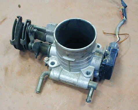
This year we are going to run an LM-1 Innovative wide band air/fuel mixture sensor and controller. The controller will give us real-time air/fuel mixture readings during the run and it will also record those readings for up to 44 minutes. You can then down-load the data file into a computer and graph the results. There is also an input jack on the LM-1 controller for up to 4 additional inputs. They can be anything you want as long as they are a 0 to 5 volt signal. Those inputs can also be recorder for up to 44 minutes (nice little data record I would say). They sell an rpm input, but we didn't have the money for that this year. I felt that if we could get throttle position input that we could then tell what our air/fuel mixtures where at idle, part throttle and WOT. Being the cheap S.O.B. that I am I went to a friends min-junk yard and got this throttle body off of a scrapped 1991 Subaru Legacy (thanks for the donation Bruce). On the right side is a throttle position sensor (TPS), which is really just a potentiometer (pot) or variable resister. This sends the computer information about what position the throttle is in and how fast it is opening or closing on a fuel injected car.
.........................
On the aux. input to the LM-1 controller 1 of the pins gives you 5 volts out and another is ground. The rest are the 4 input pins. I figured that I would use the voltage and ground to power the TPS that came from the Subaru. I used my volt/ohm-meter to figure out which wires were which on the TPS. John (WZJUNK) sent me a couple apple computer cables he had that had the right plug on one end to use in the input of the LM-1 controller. I used my volt/ohm-meter to see which wires on the Apple cable went to the correct pins on the input to the LM-1. Then I cut the plug off the other end of the Apple cable and soldered the wires on the cable to the correct wires on the TPS.
I have a bung in my GMC's header collector for the wide band O2 sensor. I put the wide band O2 sensor in the bung and hooked the LM-1 controller to it and also into the cig. lighter for 12 volts and to the apple cable hooked to the TPS. I ran the motor for air/fuel readings and moved the TPS by hand to see if the LM-1 controller was collecting the data from it. I did this for a few minutes and then took the controller inside (it easily unhooks from the various cables) and down-loaded the data file onto my computer and use the LogWorks program that comes with the controller and wonders of all wonders I had two nice graphs overlaying each other. One was the air/fuel and the other was the TPS opening and closing.
............................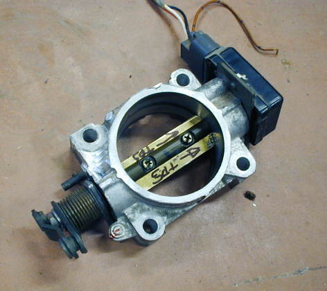
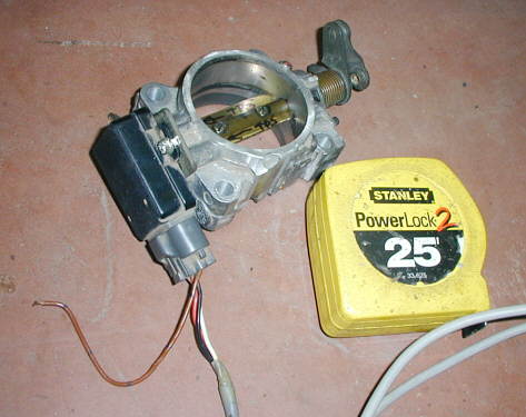
I thought the throttle body was larger than needed, so after about 30 minutes in the Mill it was whittled down to the size in the preceding picture and this picture. I also cut the butterfly in the middle of the bore down so that the throttle body can be mounted flat and the bell-crank will turn without the butterfly running into what the throttle body is mounted against. I'll use the 4 holes in the base to mount it to a bracket somewhere in the engine compartment and run a small chain from the bell-crank on the left side to the throttle linkage on the motor. So a couple hours work and a free throttle body will get us throttle position readings along with our air/fuel readings.
For a more complete description of how I built and wired this go to this page.
Now go to the next page and see the finished car pictures. I think John is bodyman extraordinary!!!!
............................................................................................ Next Page
..................................Back to Hooley's 2004 Bonneville Experience Story