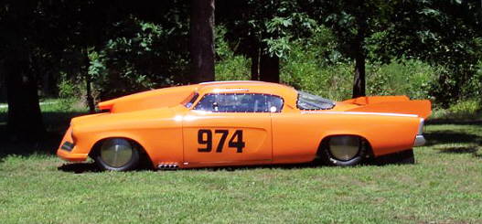
This project started since we wanted to run a throttle position sensor (TPS) and collect data from it at the same time we were collecting data from the LM-1 Innovative wide band air/fuel mixture sensor and controller while running Hooley's Stude at Bonneville in August 2005.
...........................
The controller will give us real-time air/fuel mixture readings during the run and it will also record those readings
for up to 44 minutes. You can then down-load the data file into a computer and graph the results. There is also
an input jack on the LM-1 controller for up to 4 additional inputs. They can be anything you want as long as they
are a 0 to 5 volt signal. Those inputs can also be recorded for up to 44 minutes (nice little data record I would
say). They sell an rpm input, but we didn't have the money for that this year. I felt that if we could get throttle
position input that we could then tell what our air/fuel mixtures where at idle, part throttle and WOT.
.................................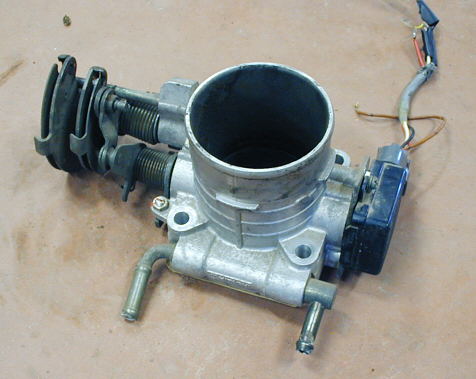
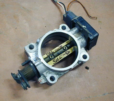
Being the cheap S.O.B. that I am I went to a friends min-junk yard and got
this throttle body off of a scrapped 1991 Subaru Legacy (thanks for the donation Bruce). On the right side is a
throttle position sensor (TPS), which is really just a potentiometer (pot) or variable resister. This sends the
computer information about what position the throttle is in and how fast it is opening or closing on a fuel injected
car.
....................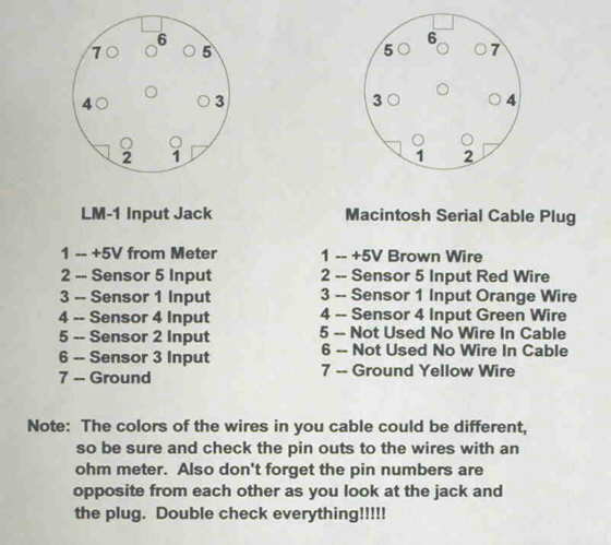
On the aux. input to the LM-1 controller one of the pins gives you 5 volts out and another is ground (pins 1 & 7 on the left side of the diagram above). The rest are the 5 input pins ( I think one is reserved for the RPM, but this could be wrong ). I figured that I would use the voltage and ground to power the TPS that came from the Subaru. I used my volt/ohm-meter to figure out which wires were which on the TPS ( see the right side of the above image ). John (WZJUNK--my good friend and fellow crew member)) sent me a couple Apple Macintosh serial cables he had that had the right plug (Mini - DIN7 or DIN8) on one end to use in the input of the LM-1 controller. I used my volt/ohm-meter to see which wires on the Apple cable went to the correct pins on the cable plug to match the input jack of the LM-1 ( see the right side of the above image ).
CAUTION: Be sure and use your volt/ohm meter to make sure all of the pin outs and wires are correct. The colors I have above could possible be different with different cables.
...................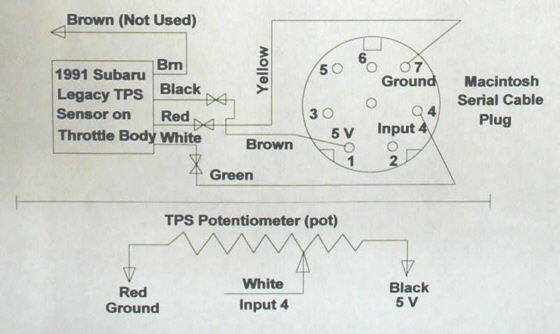
Then I cut the plug I wasn't going to use off one end of the Apple cable and soldered the correct wires on the cable to the correct wires on the TPS (see the drawing above, but again make sure your wiring is the same). I used input 4 for no particular reason. If you have a TPS and don't know which wires are which use your ohm meter to figure it out along with the drawing at the bottom of the image above. You should get the same resistance by connecting to two of the wires (Red and Black above) no matter what position the TPS is in. The resistance will vary between the output (White -- Input to sensor 4 on the LM-1 above) and the Red and/or Black wires shown at the bottom of the image above as you rotate the TPS back and forth. I have mine set up so that increasing the opening on the TPS will give a voltage rise from 0 to 5 volts. So wide open throttle is 5 volts. If I wanted it so that WOT was 0 volts then I would switch the Red and Black wires to the Input jack of the LM-1 and the White in the example above would still go to Input 4. The circuit is pretty simple. Just keep track of your wires.
.................................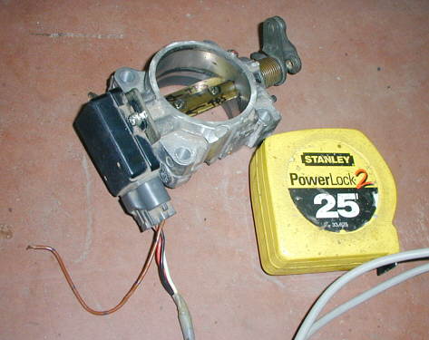
I thought the throttle body was larger than needed, so after about 30 minutes in my mill it was whittled down to this size. I also cut the butterfly in the middle of the bore down so that the throttle body can be mounted flat and the bell-crank will turn without the butterfly running into what the throttle body is mounted against. I'll use the 4 holes in the base to mount it to a bracket somewhere in the engine compartment and run a small chain from the bell-crank on the left side to the throttle linkage on the motor similar to how a cruise control is hooked up. The brown wire above is not used and I'm not sure of it's purpose in the donor car. You can see the Red, Black and White wires that were soldered to the Yellow, Brown and Green on the Macintosh cable.