...Return To Mine & Other Bonneville Car Construction Pages
.Previous Page...............B'ville Car Index Page.........................Next Page
.............................................. Idler Sprocket Part II
On this page I'll show you how I finish making the idler sprocket :-) and on the next page I'll tell you why I probably won't use it :-(. This might be boring unless you want to see how I machined these pieces so you might want to just skip to the bottom of the page for the final assembled piece.
........................................
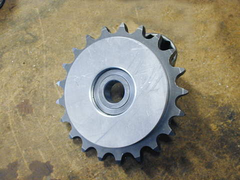
I had left off in Part 1 with the sprocket machined and sent in to be case hardened. I got the sprocket back from Randy at Advance Precision in Oregon ( see "Parts Used") and continued making my idler sprocket.
...................................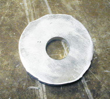
I needed a spacer to fit between the bearing and sprocket. I'll go through the steps here that I use to make a part like this. Remember I haven't had any training on the mill or lathe, so there might be a better way. I picked a piece of scrap aluminum I had and scribed a circle on it about a tenth larger than the final piece. Then I cut that out using my saber saw with a metal blade. Next using the mill I drilled a 3/4 inch hole in the center.
.............................. .
.
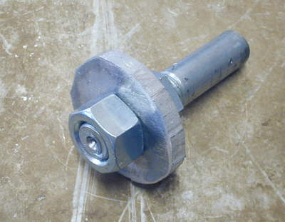
I mounted that piece on a cut-off 3/4 inch bolt with two nuts.
................. .
.
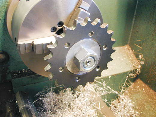
Then I mounted the bolt and piece in the 3 jaw chuck and turned the O.D. down to the point the piece would fit inside the sprocket. We are now 1/2 done.
...................... .
.
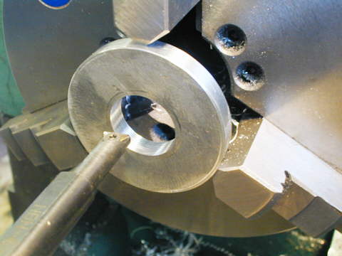
I then mounted the piece in the 3 jaw chuck holding it on the O.D.. If you ever get a lathe get at least a 12 inch one so you can easily hold larger pieces. Using a boring bar I started from the 3/4 inch hole and enlarged the center.....
..................... .
.
.....out to the correct size...........
..................... .
.
............for the bearing to fit inside the I.D. of the new piece.
............................... .
.
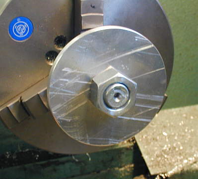
Next up was making two side plates to hold everything together. Once again I used my saw to cut out a rough circle and drilled the 3/4 inch hole in the center and mounted it to my cut-off 3/4 inch bolt and proceeded to turn it to the proper O.D.. I just Finnish that in this picture.
..................... .
.
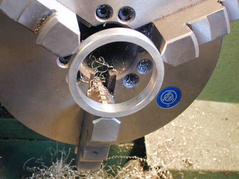
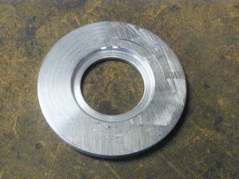
Holding the piece in the chuck by the O.D. I cut a recess into the piece as the bearing is thicker than the sprocket. The recess is 1/2 the thickness difference between the sprocket and bearing thickness. The other 1/2 minus a "touch" will go into the piece for the other side that was made the same way. After boring out the recess I bored the center out so that the piece will just grab the bearing by the outside race.
...................... .
.
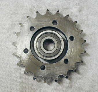
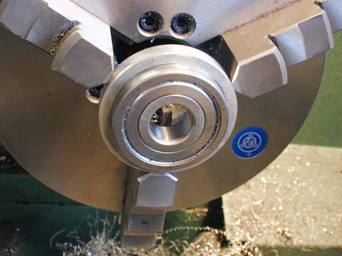
Here is the almost finished piece showing it laying on the sprocket and bearing.
........................... .
.
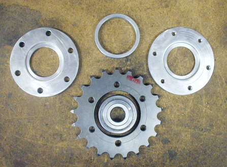
Here are the pieces that make up the idler sprocket. I finished up the two outside plates by.....
....................................... .
.
...........drilling holes in them on the mill for the thru screws. The plate on this side was drilled large enough for the screws to pass through and I also countersunk the holes. On the ..........
...................................... .
.
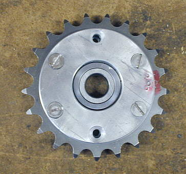
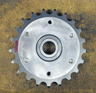
..........other side the holes were drilled with a number 7 drill and tapped for 1/4 X 20 screws. On this picture you can see an "X" on one side of the plate and another "X" on the sprocket (it is where the red mark is on the left). Since I don't have a rotary table the holes might not be perfectly symmetrical and these witness marks will help align parts the same during assembly. On the other side (last picture) you will see "O's".
Now if you go on to the next page you will see why I probably won't use this
idler sprocket. I was so close to finishing it and pretty "proud" of my work, so I decide to finish it
and show you what I did just in case someone else might want to make one of these.
..................................................................Next Page