...Return To Mine & Other Bonneville Car Construction Pages
.Previous Page...............B'ville Car Index Page.........................Next Page
.. Motor Mounts Part I & Idler Sprocket Part I
.....................
Construction of motor mounts came next as I wanted to get the motor out of the way to finish the frame. I could have welded mounts directly from the frame to the motor, but wanted to be able to change to different motor configurations possibly in the future. So I decided on weld on mounts on the frame with custom mounts depending on the motor going from the frame to the motor. Here are the mounts for the left side of the head. I have tried to triangulate the mounts both front to rear and side to side. In the motorcycle the motor has also been designed in as a frame member. They know what they are doing and I don't, so I want this motor to be supported by the frame not the other way around. Also I'm trying to design for future HP increases (maybe 4 times what this motor is capable of in stock form), so I have probably over designed this aspect of the car (once again).
....................... .
.
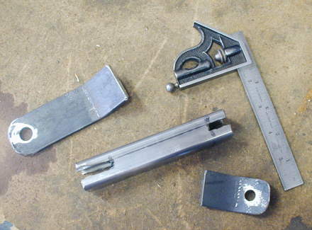
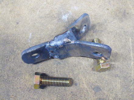
The mounts are pretty simple in construction and to make them simple each intermittent member consists of three pieces. One that bolts to the frame. Another that bolts to the motor. And a third that ties them together.
.......................... .
.
This approach made things a lot faster as I didn't have to try and figure out bolt hole locations on a single piece of metal. The end pieces are 3/16 inch strap. The center piece (on most of them) is .120 X 1 X 1 square tubing. I should have taken a little more time and notched the square tubing with the mill, but I'm not to patient some times, so I notched it with the chop saw and cut-off wheel in the die grinder.
.......................... .
.
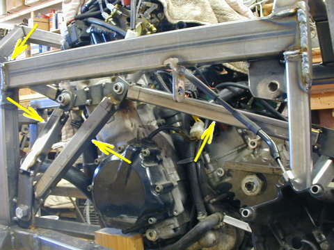
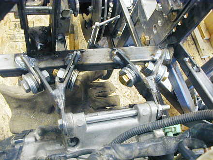
After the end pieces were bent to the proper angles (big hammer and vise). I bolted them into position and put in the middle piece and tack welded it in place. I tried to position the mounts on the frame so that they would hopefully work with a larger motor. Also I wanted the tubes to be angled some to help hold the motor in the correct position.
........................... .
.
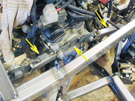
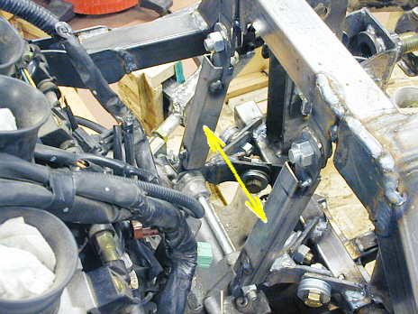
Here you can see the front (left arrow) and rear (right arrow) facing mounts that position the motor top front to rear on the car. I also put in a tie strap (middle arrow) between the two mounting points on the head so that any loading on this area that might come from the car itself would be transmitted hopefully by this strap also and not just the head and bolts into the head.
........................ .
.
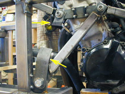
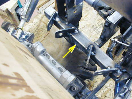
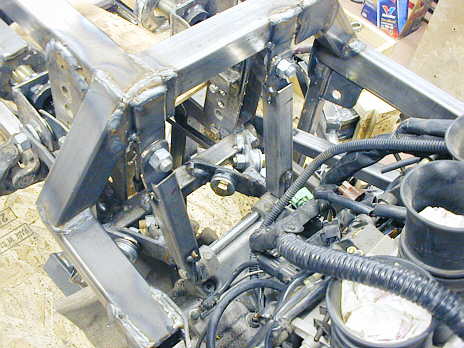
I then moved to the top rear motor mount. I started by welding in a piece of square tubing from one of the rear spring mounting towers to the other one. This point is pretty well braced to different parts of the frame. I welded in 2 sets of angled brackets to the new cross member. Here again I welded them where I thought they would work with a larger motor. I was fortunate at this point, in that Larry Forstall had just sent me some used Hayabusa cases and I could get some measurements off of them. The brown thing to the left in the picture is just a piece of wood to help keep weld splatter off the motor.
........................... .
.
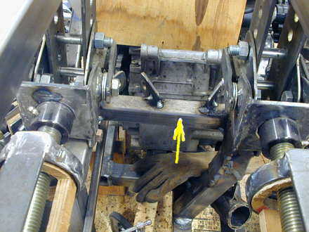
This is a view of the same area looking forward on the car. These mounts are going to probably get the highest loads of any of the motor mounts.
........................ .
.
to make the intermediate piece I cut and drilled a hole in one piece and bolted it to the motor mounting hole. Then I cut and bent two other pieces and mounted them to the angled mounts on the cross member. Then I tacked the three pieces together.
............................ .
.
I removed them and finished welded them all together. Some day when I have more time (right!!) maybe I'll remake some of these ugly steel pieces out of some nice aluminum. I'm hoping that these get the job done for now.
............................ .
.
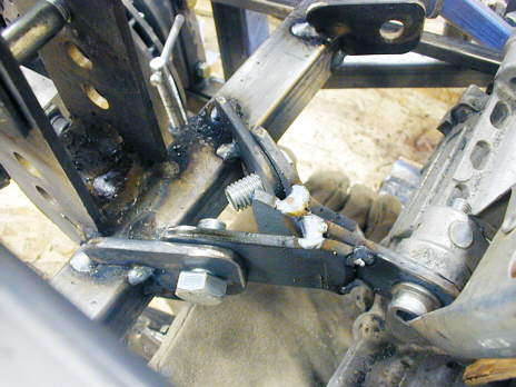
I preceded to duplicate what I did above for the left side mount (right side of the picture). Ignore all the washers on the bolts. I didn't have any bolts short enough at the time of constructing these pieces.
......................... .
.
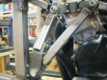
The mounts that I just made in the last couple pictures will locate the motor fore/aft, but not vertically. To do this I made two more mounts that come down from the top of the frame to the top rear motor mount on the motor.
......................... .
.
Looking at these from the other side of the motor. Most of the mounts on this page are only tack welded at the time the pictures were taken. I still at this point have to make one mount for the top of the motor at the head on the right side and the bottom rear motor mounts. That will come next.
......................... .
.
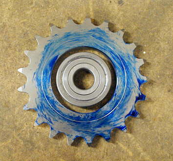
In the middle of making the motor mounts I started on the idler sprocket for the chain drive. I found a couple idler sprockets on the Internet, but couldn't really find what rpm's they were good to. In the process of figuring the rpm this idler might spin at I quickly became aware of the tremendous speeds the chain travels at in high speed bikes and cars. I figure that this sprocket will be spinning at anywhere between 8000 to 11,000 rpm depending on the speeds I'm hoping this car will eventually reach. I research sprockets as best I could on the Internet and then called MRC and talked to a tech guy and came up with the double shielded bearing, shown below, that is good to over 14,000 rpm. There is more on the sprocket and bearing and where I got them on ( THIS PAGE ).
........................................ .
.
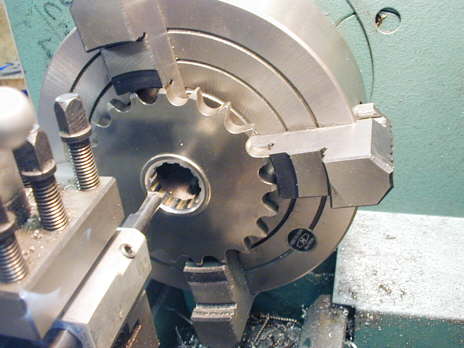
The sprocket presented a problem as I needed to machine it to work with the bearing. Randy at Advance Precision in Oregon was welling to send me a sprocket that was not yet case hardened. This way I could machine it and then send it back to him to be case hardened. I found out that the case hardening procedure can change the hole I bored in it (two pictures up) by a couple thousands. To over come that I decided to bore the sprocket's center out so that when I get it back I'll machine a sleeve to go between it and the bearing.
.............................. .
.
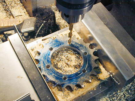
I need to also make two side plates that will retain the bearing, sleeve and sprocket so that they become one unit. To do this I drilled six holes in the sprocket.
.......................................... .
.
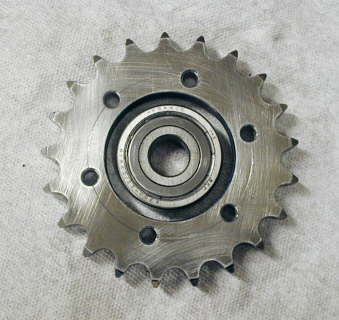
Here is the sprocket ready to go back to Randy to be case hardened. I've sent
it off and when it returns I'll try and see if I can finish the complete assembly so I have an idler sprocket.
..................................................................Next Page