Construction of my Bonneville Lakester- page 136
...Return
To Mine & Other Bonneville Car Construction Pages
.Previous
Page..............B'ville
Car Index Page..............Next
Page
==============================================================
...........--
Bellhousing Adapter Plate for GM Atlas 2900 --..
==============================================================..............................
One
reason for switch from a motorcycle engine to a car engine was that I
wanted to run a more conventional drive-train. I specifically wanted
to run a
G-Force 101A transmission like the one we were running in
Hooley's Studebaker. You can easily change the gear ratios for 1st,
2nd and 3rd gear and can run 3rd gear as an overdrive 4th gear with
the old 4th becoming a 1 to 1 3rd gear. I also needed to run either a
SFI scattershield/bellhousing or make one.
The
back of the 4 cylinder Atlas 2900 and also the 5 cylinder and 6
cylinder Atas engines do not have the bellhousing bolts in the same
pattern/location as SBC's and BBC's. One thing they do have in common
though is that the dowels that locate the bellhousing are in the same
place. One can make their own adapter plate to go between the block
and the bellhousing by taking a piece of steel and drilling the 2
holes for the dowels. Then put some bolts with sharpened ends in the
block and locate the plate on the dowels and tap the plate against
the bolts to mark the plate. Then drill the plate for the holes to
attach the plate to the block. Next do the same thing by locating the
plate on a chevy bellhousing and drilling and then tapping a second
set of holes for the bellhousing. Of course then you need to cut the
center out and the outer perimeter also. While the above is possible
I took the easy route and one that didn't cost that much.
I
ordered...
....
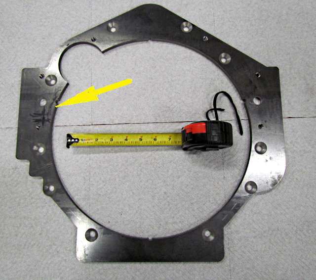
the adapter plate above from Marc at EMTechMotorSports.com.
It came also with the flathead allen bolts need to mount it to the
back of the block. If you go this route do yourself a favor and just
order the adapter from Marc. They are price very reasonably and fit
like a glove. Below you will see that I had to do some minor work on
the plate to make it work on the 4 cylinder motor since the plate was
made for the 6 cylinder which doesn't have the balance shafts. The
posed a slight interference problem. Even with the small amount of
work that had to be done to the plate to make it work it was
definitely worth the price and then some. It fits like a glove and
the dowel holes and mounting holes to the block and the tapped holes
for the bellhousing are all right on the money.
So
let's get to mounting the plate on the motor.
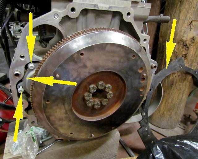
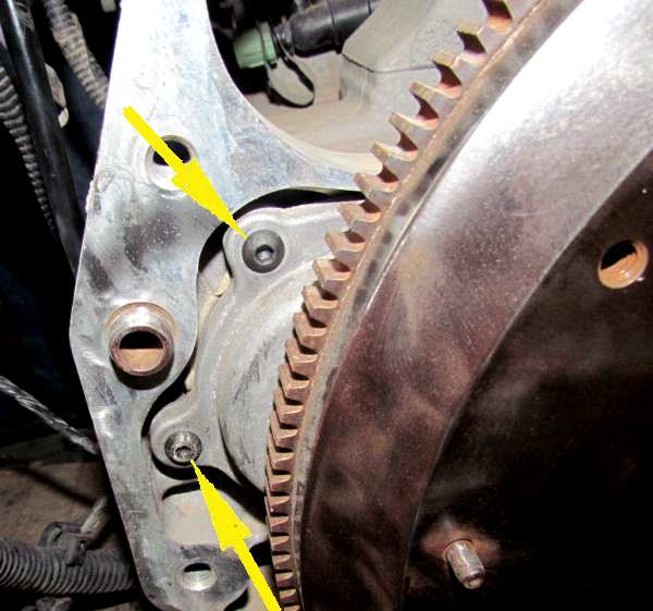
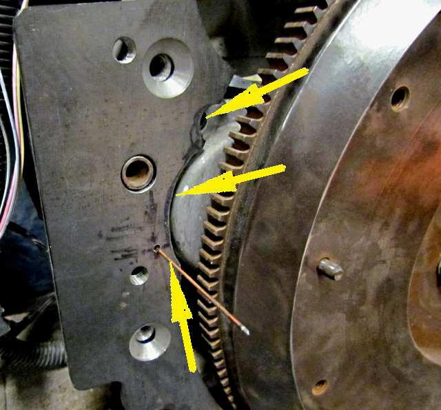
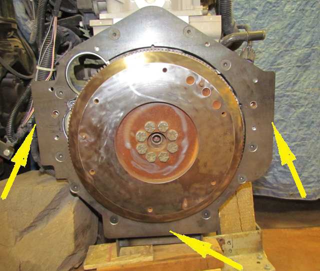
Above
the adapter plate is off to the right of the motor, right top arrow.
The problem area is shown by the 3 left arrows. The round looking
cover is covering the end of the balance shaft on the left side of
the motor and the top and bottom arrows point to two of the bolts
that hold it in place. Part of the cover and the two bolts contact
the adapter and prevent it from going on the back of the block flush.
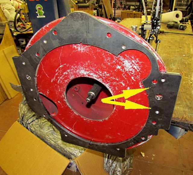
Here
the adapter has been bolted to the front of the SFI
bellhousing/scatter shield that is required by the SCTA rules and
also needed to mount the transmission and house the clutch.
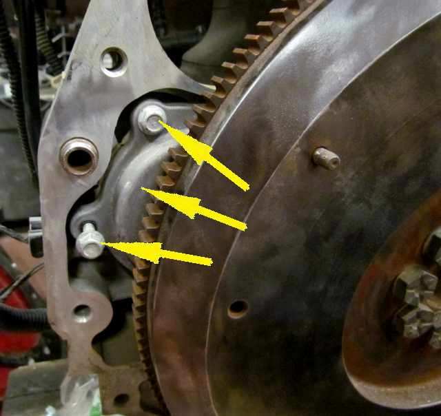
A
closeup of the same area with one of the bolts partially backed out.
Here
the bolts have been replaced with metric button head screws that are
much smaller. They still stick up enough that the adapter hits their
heads before it bottoms on the back of the block. It also hits the
rounded part of the balance shaft cover that is held on with the
screws. I did grind some off the bottom screw head to see if it would
clearance but it didn't and I didn't like the fact that the allen
wrench no longer went into the head very far so replace the screw
later with one that had a stock height head.
The
left arrow above points to the area where the screw hits the adapter
and noticed that it is just above and to the right of the threaded
hole for a bellhousing bolt below the locater dowel pin hole.
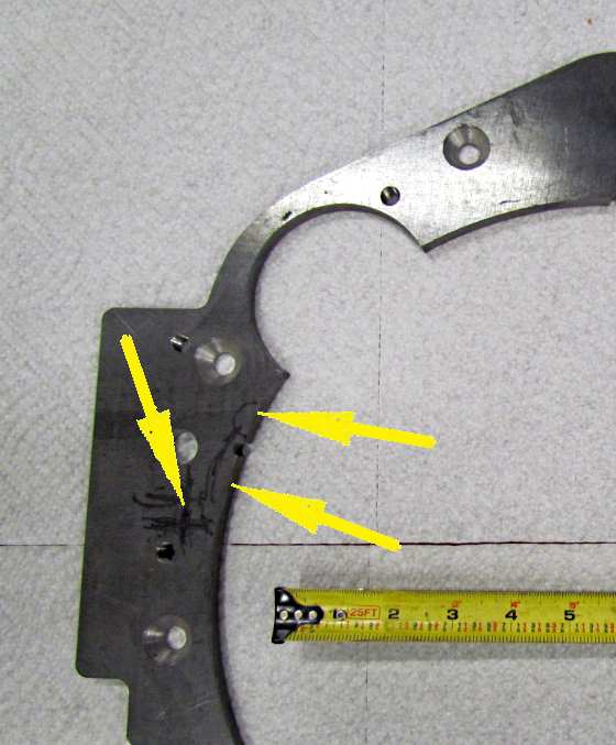
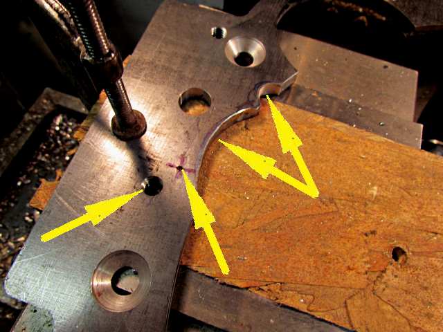
The
top right arrow points to where the top allen screw is and the bottom
right arrow points to where the cutout needs to be to clear the
balance shaft cover. There is a lot of meat in the adapter in this
area so taking some out will not effect the integrity of it. The only
real problem is the area close to the threaded hole, left arrow..
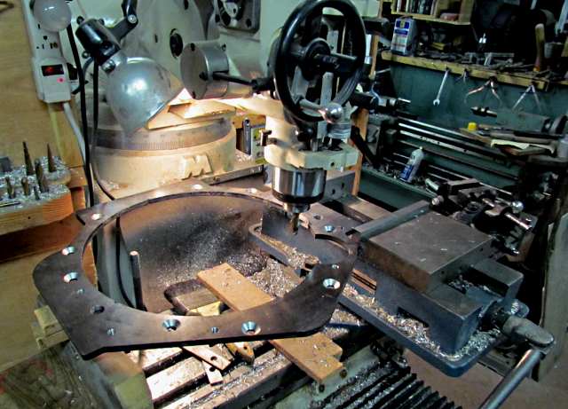
Here
the adapter has been mounted in the vise on the mill's table. I have
a mill so used it. You could also easily use a grinder for what I've
done next. This is not precision work.
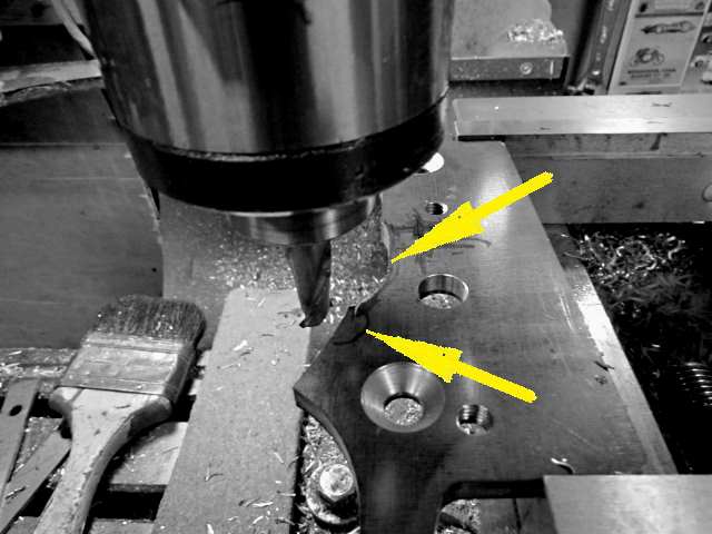
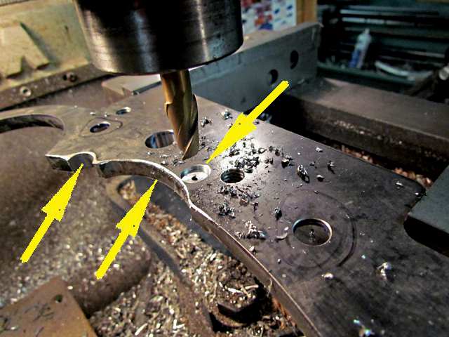
First
the area for the round cover, top arrow has been cut out. The next
step was to cut out the smaller area for the allen screw, bottom
arrow. Note this is not the area where the bottom screw is located
that is near the threaded bolt hole. We will deal with that another
way.
With
the initial clearancing taken care of, top right arrows the problem
of the other allen head screw was addressed. If you just cut into the
plate like was done above you start to get very close to the threaded
hole, left arrow and I didn't want to do that and weaken the adapter
in that area so instead located where the allen screw was the best I
could and then drilled through the plate at that point, middle arrow
with a small bit.
..((
Note that the intial clearancing worked out well, top 2 arrows. )
Then
I mounted the adapter on the block without the lower allen screw in
the balance shaft cover. I took a small diameter welding rod and
inserted it through the adapter and into the allen screw hole and
felt around to see if I felt the pilot hole was centered. It didn't
feel exactly centered so took note of which direction it was off
and....
...
took the adapter back to the mill and used an end mill to go part way
through the adapter using my pilot hole and mental offset note as a
guide. You only need to go into the plate far enough for the head of
the allen screw to not contact the adapter. There again you don't
need a mill, a drill bit would of worked.
I
feel this doesn't effect the strength of the adapter in the area of
the threaded hole near as much as if we would of cut in from the
inner surface like was done above, 2 left arrows.
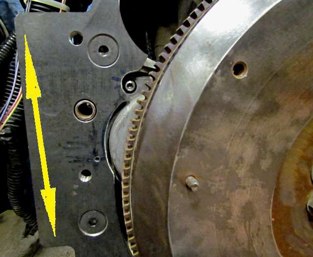
Here
the adapter has been mounted flush with the block with the flathead
allen bolts that Marc supplies. The double ended left arrow notes an
extension that.....
....
is on both sides of the adapter that you could weld to in order to
use the adapter as a mid-engine mounting plate which I will probably
do. The bottom could also probaby by used if needed.
This
is a great adapter that Marc offers and I highly recommend it. There
is a possibility that it might come pre-clearanced in the future for
the 4 and 5 cylinders so you don't have to do it yourself. If you do
don't let that stand in the way as even with a grinder and a drill
you shouldn't need to spend more than an hour or two on doing this.
No where near the time it would take to make an adapter plate. Since
the 4200 6 cylinder doesn't have the balance shafts none of the above
has to be done to use the adapter on that engine.
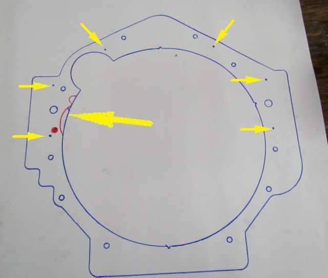
I
made a full size pattern of the adapter on a sheet of white paper
that shows the shape before and after the modification, single large
arrow. The small arrows point to where the transmission or
bellhousing (if a manual) mounts to pre-threaded holes in the new
adapter.
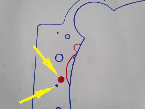
An
enlargement of the area that was clearanced to the red line. The
lower left arrow points to the center of the threaded hole used to
mount the chevy bellhousing.
If
you need to mount a SBC bellhousing for a standard transmission or
one of the automatics to one of these engines in the Atlas line
contact Marc at EMTechMotorSports.com
.
=============================================================
..........................................................Next
Page