...Return To Mine & Other Bonneville Car Construction Pages
.Previous Page...............B'ville Car Index Page.........................Next Page
..............................-- Seat Part I & Some Gussets --
................... .
.
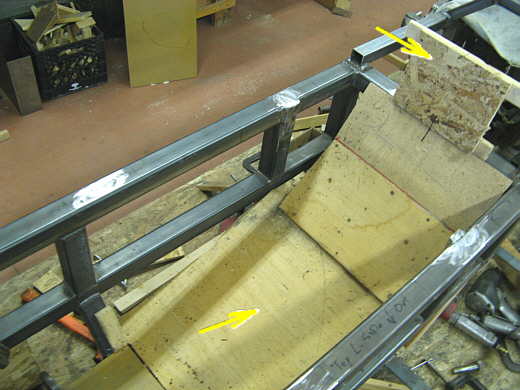
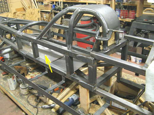
While Phil was over and while he was welding the cage and working on the right side side pod and other things I started on the seat (notice he gets lots more done than I do). Here the cage is off and the arrow is pointing to the wooden seat that I have had in for some time. It is at a couple different angles. I wanted to make the new one as close to this as possible, but it will sit 1/2 inch lower due to the thickness of 20 gauge steel vs. the 1/2 inch plywood.
................... .
.
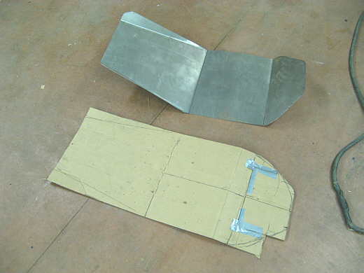
I jammed a piece of cardboard down over the wood seat and cut it into a pattern. I transferred that pattern to the 20 gauge cold rolled steel and cut it out with some electric hand shears and manual ones. I used the sheet metal press break I had built some years ago to create the bends.
................... .
.
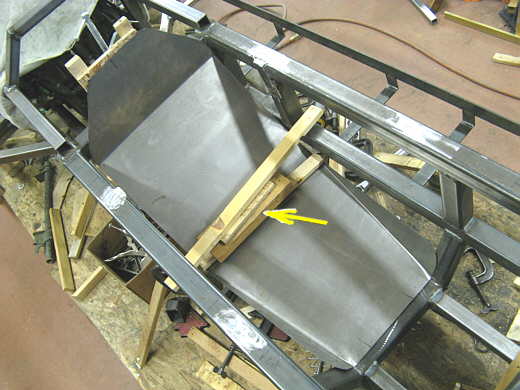
Here the seat is clamped into position with the cross boards. They are needed until I weld on tabs to the frame to locate the seat as it would just slide down at this point. The sides of the cockpit will probably be covered with some .030 aluminum I have. The seat sits directly on lower cockpit frame members (see page 37).
................... .
.
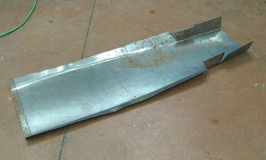
Next I made a pattern and cut and bent the front part of the floor/seat. The cuts on the right side are to clearance this piece around the steering bell cranks (see last picture on THIS PAGE). The cuts will get pieces welded into them and the whole think will be finished so as to not have any sharp edges.
................... .
.
Here the arrow points to the forward seat extension/floor. The seat will stay in two parts for easy of removal from the car.
................... .
.
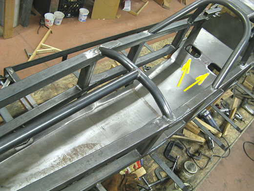
With me in the car Phil marked the spots where the seat belts had to be attached for a lay down seating position following the rule book. The slots (arrows) in the seat are for the shoulder belts.
................... .
.
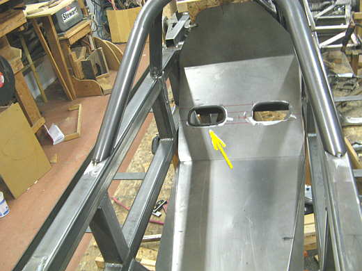
I took a piece of small diameter rubber fuel line and cut it half way through for its length. Then I ran it around the hole to see if that would work (left arrow). I seems to work fine. After I paint the seat I'll cut some more hose and use some weather strip adhesive to really secure it to the seat. The pull of the belts is down through the hole in a straight line and does not bend over the hole opening so the belts don't really chaff on the holes, but I still want to cover the edges.
................... .
.
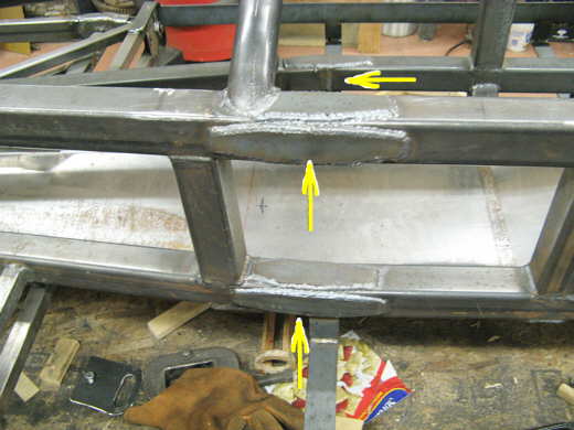
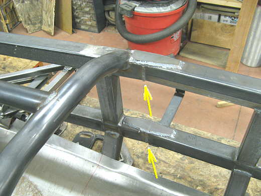
At Speed Week a year or so ago I think Jim Miller had said he had seen my construction pictures and that to get through tech they would want the joints on my frame reinforced where the frame in the middle of a run between two up rights (arrows) has an angle joint in it. I was going to eventually do that anyway and here is what Phil did while he was over in addition to everything else he did.
................... .
.
In this picture you can see the joint better (arrows). At the moment we have diamond plates on two sides of each frame rail. I need to see if they want them on all four sides. Not a big deal and will probably do it anyway. Phil just ran out of time at this point and had to head for home. A big problem for us is the deer in the area. There are tons of them on the roads between his place and mine and neither of us want to drive the route at night if we can help it. When Sparky was here right before Thanksgiving he had the unfortunate circumstance of hitting one 4 miles south of me at 9 in the morning.
................... .
.
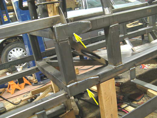
Phil also made these plates that tie the crossmembers at the rear of the cage to the horizontal frame members that run forward on each side of the cage. Thanks for all the help Phil!!
..............................................................Next Page