...Return To Mine & Other Bonneville Car Construction Pages
.Previous Page...............B'ville Car Index Page.........................Next Page
........................... Metal Cage (cockpit) - Part I
.......
It it finally time for the wooden cage/cockpit to go. I've enjoyed/endured some different comments about it. All kidding aside I personally feel it was very beneficial in helping to lay out the cage this way. You will see in the following pictures I've made a couple slight changes to it. Also, and I'm sure you are tired of hearing this, make yourself some kind of build table like I have done. It makes changes and accurate layout very easy. You can measure off a centerline drawn down the middle and/or off the straight side edges when laying out components of the car. Besides that it gives you a flat/level surface that you can use a level and square on when laying out frame/suspension members.
............... .
.
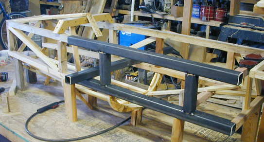
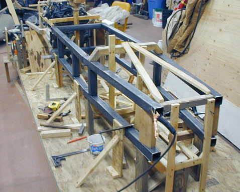
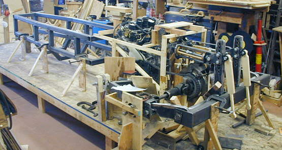
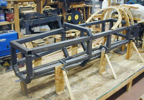
I started the metal cage by removing wooden pieces down one side of the car and replacing them with steel ones. At the same time I made the duplicate pieces for the other side of the car seen laying on the table in this picture. I mocked up the cage with 2 X 2's which are really 1 1/2 X 1 1/2. To keep the inside of the cockpit close to the same width I positioned the new steel pieces, which are full 2 X 2 inches X .120 square tubing, so that they were 1/4 inch inside of and out side of the wooden pieces they replaced. I positioned the tops of the top members where the tops of the wooden ones were and the bottom of the bottom members where the bottoms of the wooden ones were. This kept the height of the cockpit the same and the interior width is now 1/2 inch narrower and the outside width 1/2 inch wider (probably more info than you wanted to know ;-))
............. .
.
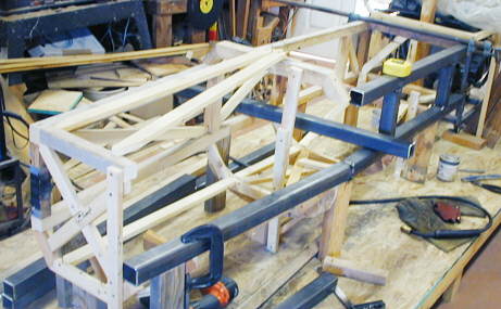
After finishing the main horizontal and uprights on the left side of the car I moved to the right side.
..................................... .
.
A view from the front of the cage. I had to put in some temporary wooden uprights to hold some of the old pieces in place. I also had to shorten the wooded crossmembers 1/4 inch on each end to accommodate the 1/2 inch wider frame members.
................ .
.
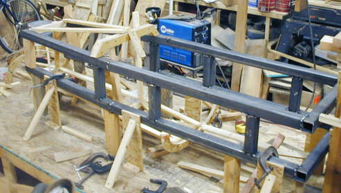
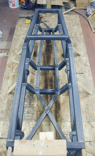
Along the bottom rails you can see wooden uprights screwed to the table (another benefit of a wood table) with bracing. These aligned and positioned the frame members as I was welding everything up. I initially tack welded the pieces at the corners and then later (see final pictures) completely welded the joints. I was really worried about warping of the frame from all the welding, but by jumping around on the joints it stayed with in about 1/16 of an inch of where it was to begin with.
.......... .
.
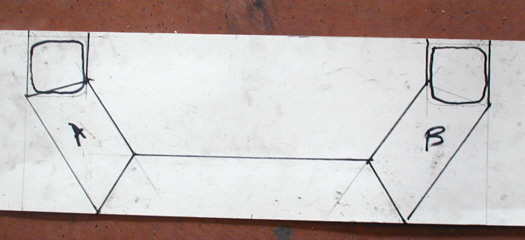
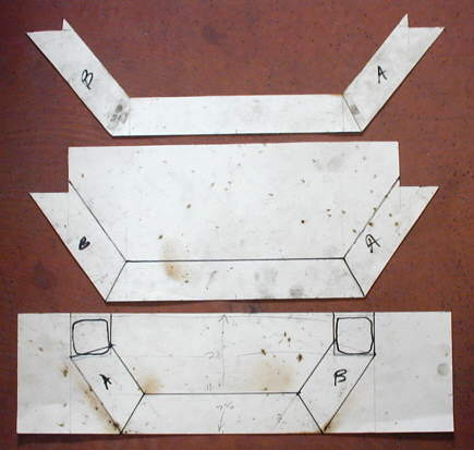
To make the bottom crossmembers I made some full size paper patterns to help with the angles. Once I had the frame width and the depth of the cross member I could make these in just a couple minutes. They saved a lot of time cutting and grinding these pieces.
................ .
.
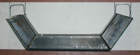
Here I have cut and ground the three pieces of the crossmember using the pattern. Next I tacked them together on the pattern and then took them to the car......
.......................... .
.
Where they were welded into place on the side rails. I followed that up by cutting the uprights and welding them in.
...................... .
.
Here is a picture of the three bottom crossmember patterns.
...................................... .
.
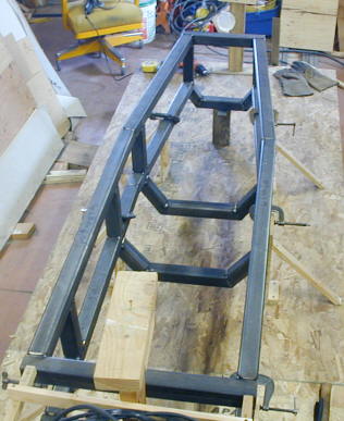
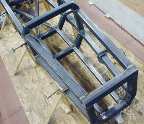
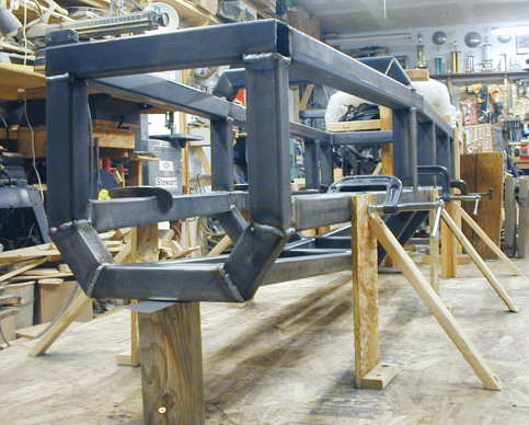
The three crossmembers installed on the car. The bottom of the car body will be rounded and about 5-6 inches off of the ground. The crossmembers are dropped to give me more room in the cockpit and to keep the height of the car to a minimum. The lowest point on the car will be the drain plug on the bottom of the motor, which will be about 5-6 inches off of the ground.
............................................ .
.
A view from the front at this stage of the cage.
............. .
.
This is a better view of the supports to locate the frame/cage. You can also see how the bottom front of the cage is gaining altitude off of the table. This is being done to help fit into the shape of the drop tank that I'll try and use for the front of the car.
............ .
.
I put this picture in to give you some idea of the overall layout of the car at this point. After I finish most of the cage I'll move it forward from its present position about 18-22 inches and start building the rear frame off of the back of it. I have all of my rear suspension/control arms/etc. where I want them and I don't really want to move them around until the frame is built to connect them all together. I need more room between the motor and cage for exhaust and intercooler, so I needed to either move the cage forward or all of this stuff back. I figured it was easier to relocate the one piece cage forward.
............ .
.
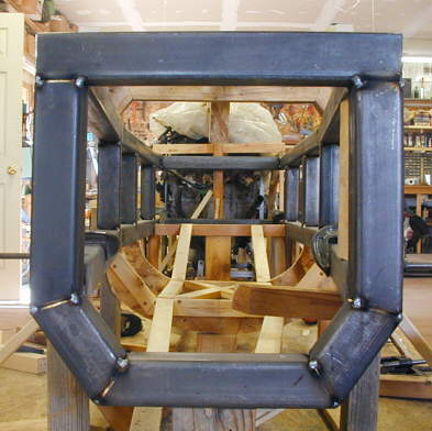
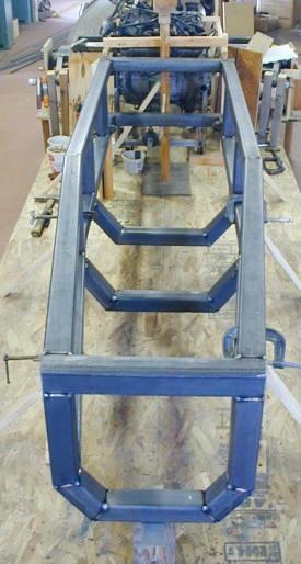
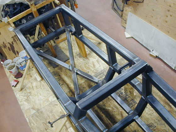
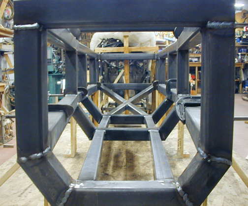
After the bottom crossmembers I started on the bottom cage bracing to protect me from the bottom and to make the cage more structurally sound. I wanted to triangulate it so I added this back "X" section that will be under my back. I'm also going to have to make attachment points for my belts after I get the seat figured out. The top crossmember shown here is made, but not welded in. The two short angled uprights are tacked to the cage, but I've just set the cross piece in for the pictures. I don't want to weld it in or the other bracing until I finish the sides of the frame and the seat, steering box, pedals, etc. as it will be easier to get to these pieces without the top of the cage in place.
...................... .
.
The bottom bracing for the front of the cage is shown here.
........................................... .
.
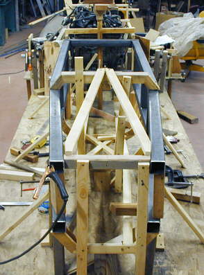
Looking down the cage from the back.
........................ .
.
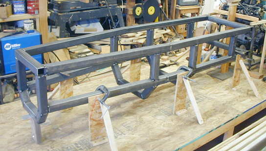
A low view from the front that shows the bottom slopping up better than the other picture.
...................... .
.
Looking down the inside.
...................... .
.
A shot with the wooden top of the cage. I'll get these hoops bent out of 1 5/8 round tubing a little later. I want to get the seat in an make sure of my headroom before I have these bent and weld them in. Next up is diagonal bracing on the sides and bracing going from the top front to the top/middle crossmember. It took about four 6-7 hour days this past week to cut and weld up the cage to this point. There were angle cuts on most of the pieces and that took a little longer, especially some the multi-angle pieces in the bottom bracing. Still it went pretty fast as I had gone through various versions of the cage in the wooden form.
It has been almost a year since I started to actually build the car and I wish I was further, but I'm happy with what has been accomplished. I hope by the end of the month at least that I'm finished with the rear frame and that I'm on to the front axles and suspension. The front looks like it is going to be pretty complicated, but not quite as bad as the back.
One final note: I've had a number of people comment on the fact that they feel I'm overbuilding this car. I told my wife yesterday that I would rather be alive and not have a record than dead with one. I realize this is is a lot of car for the 750 Suzuki and the J class 164 mph record that I'll first be running against, but with a turbo on it I'm hoping for 260 to 270 HP and eventually I would like to see a 500-600 HP 'busa motor in this car or maybe a 2 liter car motor in the same HP range.
..................................................................Next Page