..................
...............--- Swim Ladder Extension -- Pushpit Mod ---
...............................................................................--- Part III ---
...............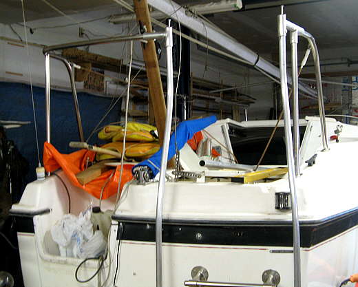
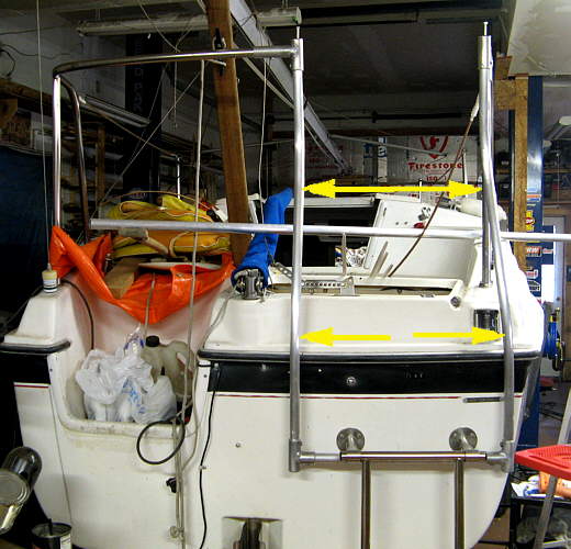
On the last page we left off with the new wrinkle free up rights. Here they are in back in .
...............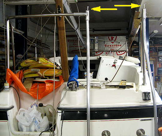
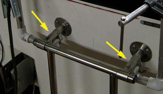
In case you have been wondering the bolts sticking out the tops of the uprights (arrows) and just there screwed into the bushings that help clamp the uprights to the top fittings. I've left them in while I take these parts apart and put them back together again during the build process. Later they will be screwed out.
In the above picture you can see how the starboard upright bows out so as to not block the marker light near it.
...............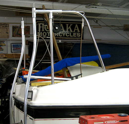
Here you can also see how it follows the curve of the port upright. This is the two plane or compound curve that had to be put in it on the previous page.
...............
On the first page this support had been made to support the bottoms of the uprights and ......
...............
.... was clamped to the bottom of the swim ladder with hose clamps. I didn't like the looks of it, so ......
...............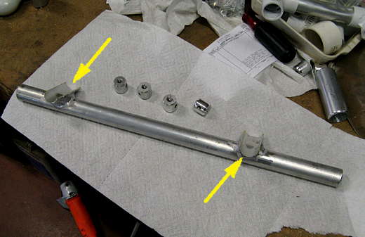
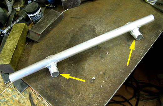
.... the tops of the short pieces of tubing were cut in half, so they became saddles (arrows).
...............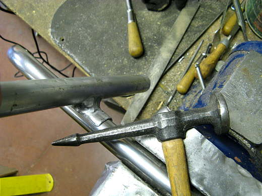
Here they have been placed on a piece of the stainless railing I cut out and using the body hammer have been worked back into a rounded shape.
...............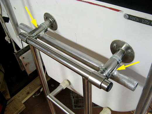
Then this piece was clamped back on the existing swim ladder. I like this better, but still might bolt this to the swim ladder at some point for a more finished look.
...............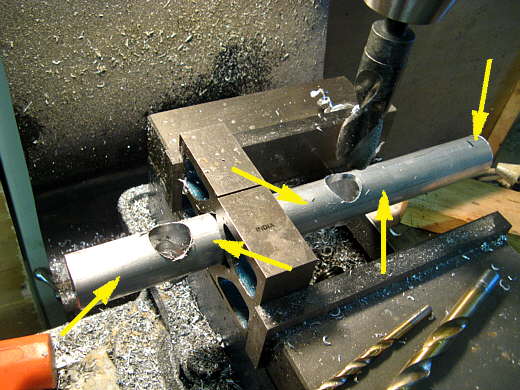
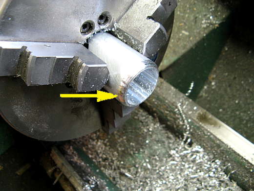
Next some fittings were needed to weld onto the uprights that would hold the new upper ladder rungs. This is pretty much how I also made the previous fittings that hold the new addition to the pushpit to the existing railing that was there. Here 5 fittings are being made. There will be two on each side of the 1 inch holes I drilled in the tubing (4 left arrows) and another made from the end of the tube. The holes are 1 inch as that is OD size of the uprights. The tubing here is 1 5/16 OD and one inch ID and is the same as I used for the previous fittings. On the end I first also drilled a .......
...............
.... one inch hole and then, since that is the largest bit I have, used the boring bar to take it out to 1 5/16 inch as this fitting will saddle another piece of tubing that size to make another Tee.
...............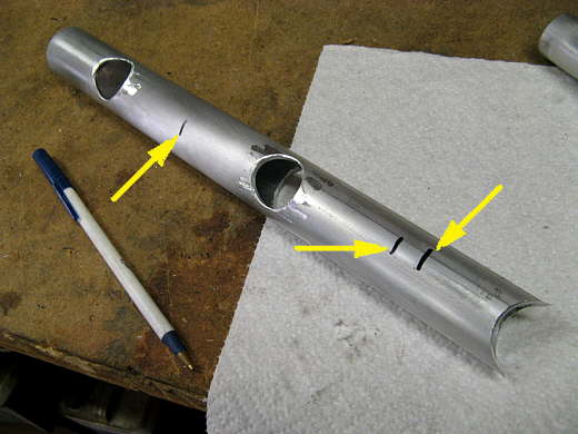
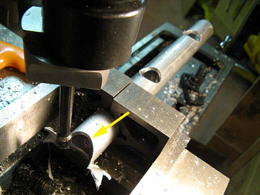
Next the tube was cut at the middle of each hole and also where the arrows are to give me 5 pieces. I notched some of the earlier ones with an end mill and the grinder as the largest end mill I have is 3/4 inch in dia.. This was much faster, cleaner and gave a perfect fit for welding.
...............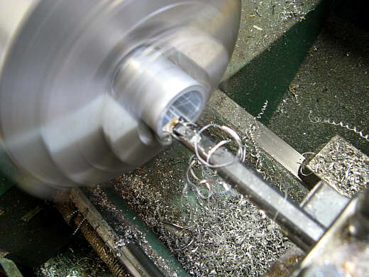
Since the 1 inch aluminum tubing I have is actually 1.050 OD I had to bore these pieces out .050 over there 1 inch stock OD size.
...............
Next I cut a 45 deg. angle on the end with a bit and then rounded that off with a file to get rid of the square end.
...............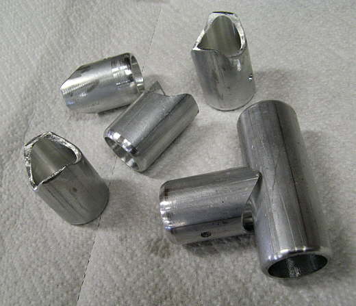
Here are the 5 fittings that were made from the pipe plus another piece at the bottom right that will make up the other leg of the Tee.
...............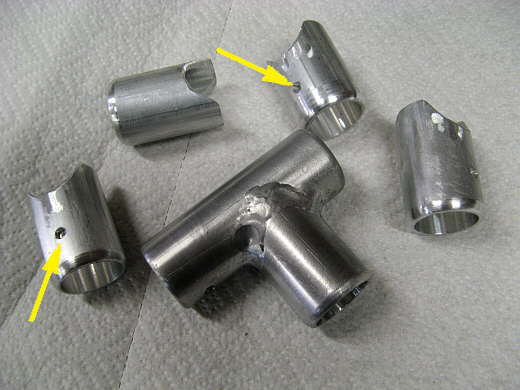
Here the Tee has been welded together and starter holes in the four pieces that will be the ends of the ladder rungs.
...............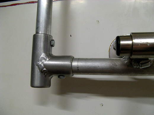
Here the Tee has been installed attaching the port upright to the bottom support using bushings like has been shown on a previous page.
...............
The next page will detail adding two more upper rungs where the arrows are located.