..................
...............--- Swim Ladder Extension -- Pushpit Mod ---
.....................................................................................--- Part II ---
...............
On the last page I was using PVC Ell's and Tee's to mock up the ladder and the uprights had bend marks in them from the bender I used. On this page and the next the Ell's and Tee's will be replaced with aluminum ones and new uprights will be bent with no marks.
...............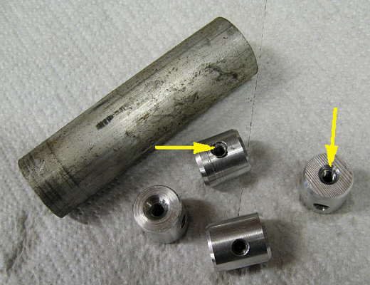
I needed to come up with a way to attach the Ell's and Tee's to the tubing. I made designed and made these bushings and more. They were turned down from the scrap round stock I had (upper left piece). They fit inside the existing stainless tubing and the new aluminum tubing. They were drilled and tapped down the center and also at right angles to the center and here is how they work.
...............
A temporary long bolt is screwed into the end so that the bushing can be inserted into the tubing to the desired depth with the other threaded hole aligned with a hole in the tubing. I had never drilled stainless and heard all of the stories about how hard it was to drill. I went up to the hardware store and bought a starter bit, a 1/4 inch bit and the next size over 1/4 inch all in cobalt and left about $20 there doing that. I didn't use a one of them. I had an idea and it worked great. I'm lucky enough to have a plasma cutter (one of the nicer pieces of shop equipment I have). I slid the ell or "t" onto the tubing and they had a 3/16 inch starter hole in them that was where I wanted my set bolt. I took a fine point magic marker and put a mark up on the tubing through the hole in the fitting. Next I took the fitting off and put my plasma cutter up on the mark and pulled the trigger. That blew a small hole right through the wall of the tubing. Then I took a normal (well nitrated HF) 3/16 inch bit and drilled the hole out to 3/16. That was easy. Next I put the fitting on so that it straddled the hole and drilled a 1/4 inch hole through the fitting and the tubing. Again easy. The hard part of drilling with the stainless is getting the hole started and the plasma cutter solved that. I'd bet you might be able to do the same with a cutting torch, but didn't try it.
Well back to using the bushing to hold the fitting to the tubing.
...............
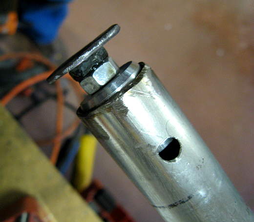
Using the long 1/4 inch bolt the bushing is pushed into the tubing until the tapped hole in it is over the hole in the tubing. Next a 1/4 inch bolt is temporarily screwed into the bushing.
...............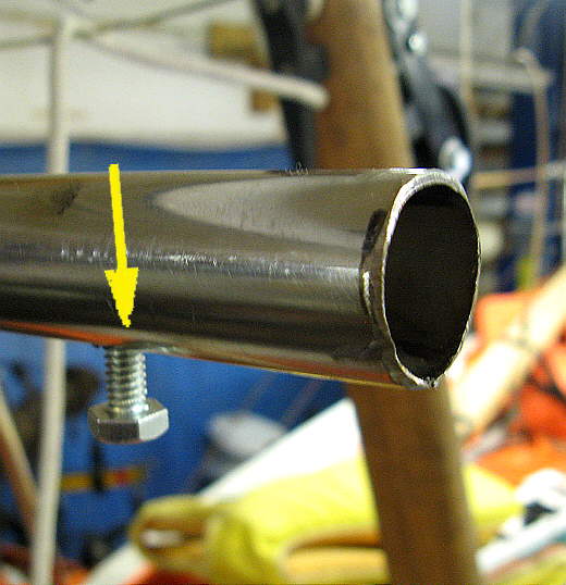
With the bolt screwed into the bushing it can't turn or go anywhere and you can unscrew the long "locator" bolt that was used to push the bushing to the correct location. After the long bolt is taken out you can remove the short bolt from the hole and the bushing will just lay in the tubing ready to go.
...............
Slide the fitting over the tubing and align the holes in it and the one in the tubing and bushing and screw in the attach bolt. Later the bolt will be changed to a stainless one and I'll put no-seize on the threads, but we are a long ways from there at this point. Note the fittings are just tacked together at this time and I'll show how they were made on the next page.
...............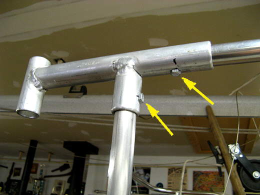
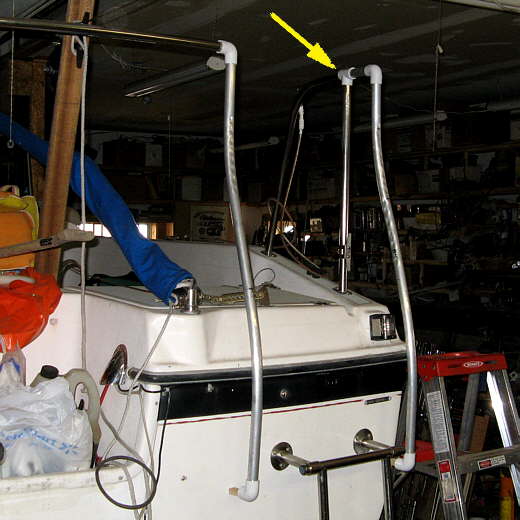
On the starboard side I had this fitting that joins the original horizontal rail, the original upright and at the left the new ladder upright. The top right arrow points to where a bushing was put in like described above. The left arrow points to where I had to place a bushing that presented a problem since there was no way to lower with a bolt to where it needed to be. By the way the reason for the bushings are two fold. One being I could have drilled all the way through the fitting and the tubing and put a bolt all the way through. That wouldn't of looked as nice as I'd have a head on one side and a nut/washer on the other side. This method allows the bolt to be hidden more. Second with the bolt all the way through if I tightened it it could have crushed the tubing or require at best a nut with a nylon insert to keep it somewhat tight. With this method the bolt can be tightened down and it pull the bushing, tubing, and fitting all together in a nice tight, non-moveable joint.
Ok back to our problem of how to locate the bushing in the blind tubing.
...............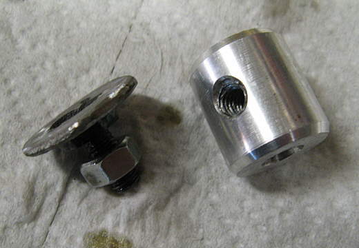
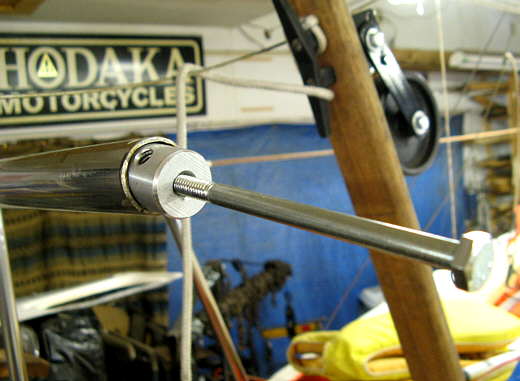
Using the TIG a washer was welded to the head of a short bolt and a lock nut was put on the bolt.
...............
The bolt was screwed into the end of the bushing at the right length that when the bushing was dropped into the tubing the washer would stop at the top and the side hole in the bushing would align with the hole in the tubing. Then the lock nut was tightened so that all of this was fixed.
...............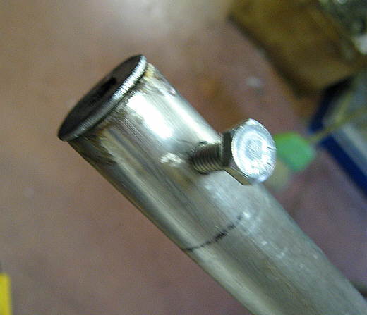
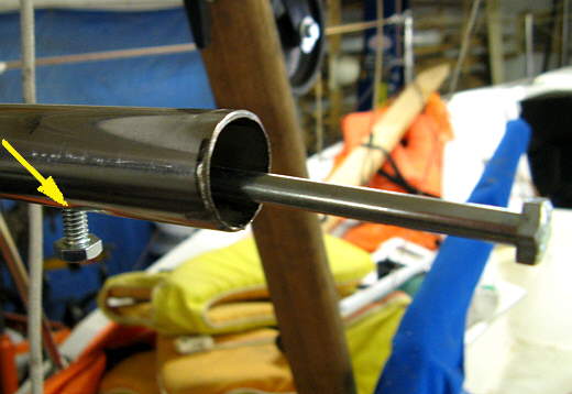
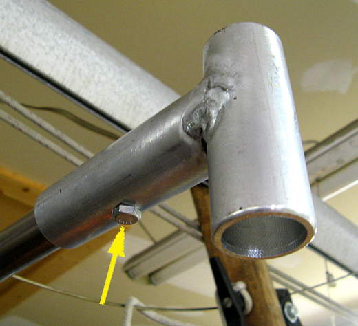
Here is how the bushing fits into the tubing.
...............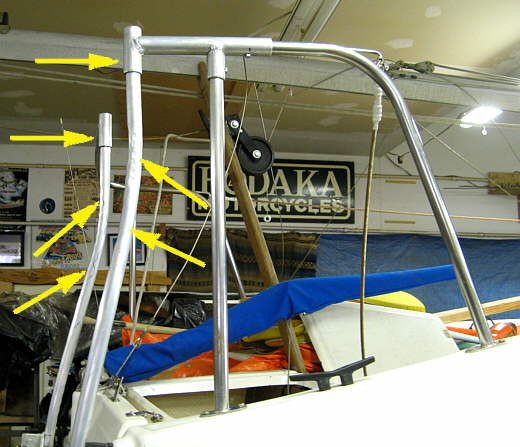
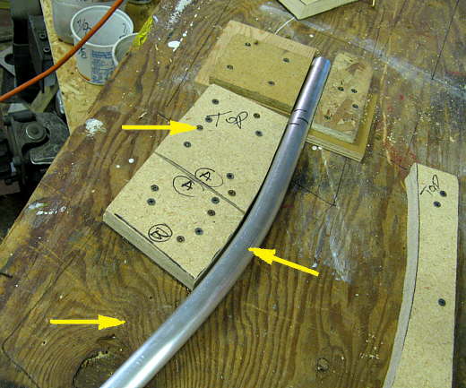
Bushings were also used on the two uprights (top two left arrows). The bottom 4 arrows point to the uprights that have all the indentations left in them from the bender I used that wasn't designed for round tubing. My plan was to use them, ugly and all, and replace them later. Well there is going to be some brackets welded to them and I hated thinking about re-doing all of those also, so I looked for a way to bend new ones without marks. First I spent an entire day making dies to go in the bender I had used that would turn it into a mandrel bender. Well the outcome of that was a disaster. The dies were good, but I was trying to bend the tubing with too small of a radius and I still ended up with indents on the test piece I tried. Next plan fill the tubes with sand and cap them like I had read about. Before doing that I decided to first make a jig to bend the tubes to the shape I wanted and when I tried it without the sand I got great bends without any marks.
Here is what I did.
...............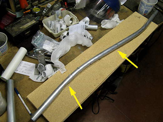
I took the port side tube with the indents and laid it on top of a scrap piece of 1/2 inch particle board I had and trace it's outline (arrows). I used the port side one as it was bent in only one plane. The starboard side one was bent the same, but was also bent in a second plane to clear the rear light on the starboard side of the transom.
...............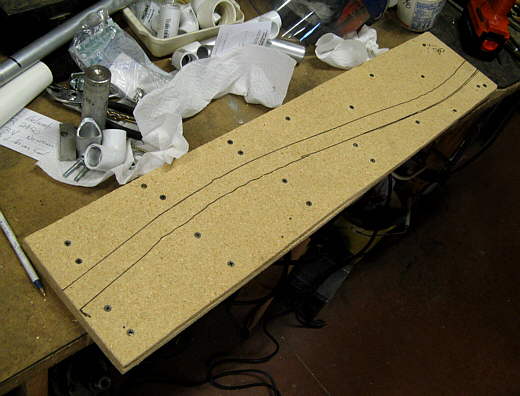
Next the first piece of particle board was screwed to a second piece of the same size. Now the two of them were 1 inch thick which is the diameter of the tubing.
...............
I cut along one line (this picture) and then along the other line. I also made a cut past the first bend and before the second one in a straight stretch of the tubing.
...............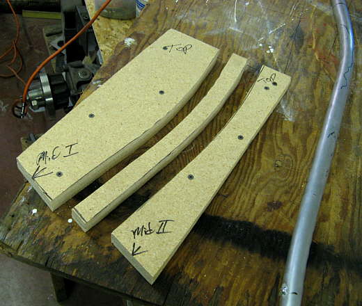
This picture shows the left and right sides of the first bend and the center waste material.
...............
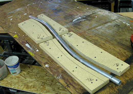
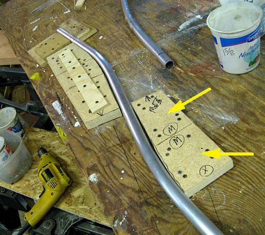
I laid the existing tube with the indents on a large piece of plywood that I use as a temporary table and screwed the inside of the first curve to it (bottom left two arrows) and screwed to stop pieces at the top of the tube to hole it in place (top arrows). The plan was to bend the tube around the first bend at this point. Well that didn't work as the tube would bend all the way to the pattern and then spring back some as shown.
...............
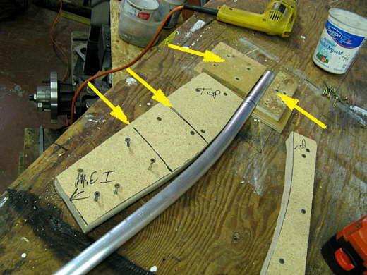
I then cut the first bend pattern into 3 parts and at first screwed just the top one to the plywood (the one with the word "top" on it). Now I could bend around it and past it a little so that when I released the tube it went back to the correct location where the second piece would be. When that was done I added the second piece (shown above) and bent the pipe a little past the bend line on the table and released it and when it went back and stayed on the bend line I .....
...............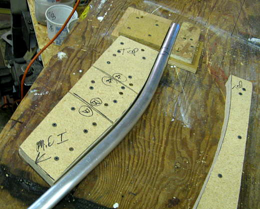
....added the third section (with the word "Mid I" on it above). At this point I had the first bend finished with no kinks or indents in the tubing. I was smiling.
...............
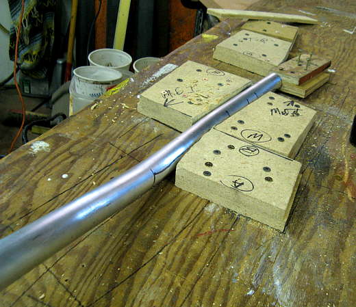
Next the pattern on the other side for the bend in the opposite direction was also cut into 3 sections and I proceeded to bend one section at a time like above. Here I've finished the first two sections of the bend and I'm bending past the second section to the point that when I released the tubing and it springs back it ends up on the bend line on the platform.
So the first one turned out great and it was on to the second one.
...............
This one I worried about some as in addition to being bent on the one plane like the other one it also had to be bent on a second plane 90 degrees to the other to clear that light. I started by making a duplicate of the first. That went find. Then I marked where it had to bend out and back in the clear the light. I held the bent tube so that the first bends were pointed towards the ceiling and then used part of the blocks I had made for the other bend and screwed them to the table and used them to bend the tube in the second direction. It worked fine. I had to hold the long end also with a pipe wrench to get leverage on it as it wanted to rotate down flat on the table as I tried to bend it. The tube was long at both ends as this point, so the wrench left no marks as I cut that extra length off.
...............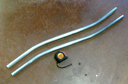
Here are the two new tubes with no marks. It is hard to see there that the second has the other bends in it, but you can see them in the pictures coming up where these two tubes are mounted on the boat. Now I can finish this and not have to re-do these, unless I decide later to do all of this in stainless.