..................
...................--- Spare Outboard Mount on Pushpit ---
Since we will be sailing quite a bit on Lake Powell and it's narrow canyons having an outboard is a must have at times. We feared getting 50-100 miles down the lake and having the 1990 Honda 8 HP die on us and then having to spend $500-1000 to get towed back to the marina. Also we wanted a dingy to explore some of the side canyons where a sailboat can't go. We got a 9 foot Zodiac and a long shaft 5 HP Nissan 4 stroke to handle the exploring needs and so that we would have a spare outboard with us. On our first sail in Colo. the Honda wouldn't start and we used the Nissan. During those 5 days out it became apparent during the morning and night visit to shore with the dog that it was nice not to have the Nissan on the Zodiac and just row it the short distance to shore. I'd seen a couple other boats with a spare outboard mounted back on the pushpit and decided to do the same.
...............
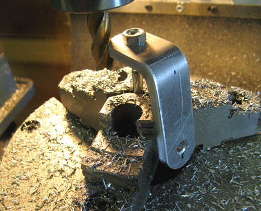
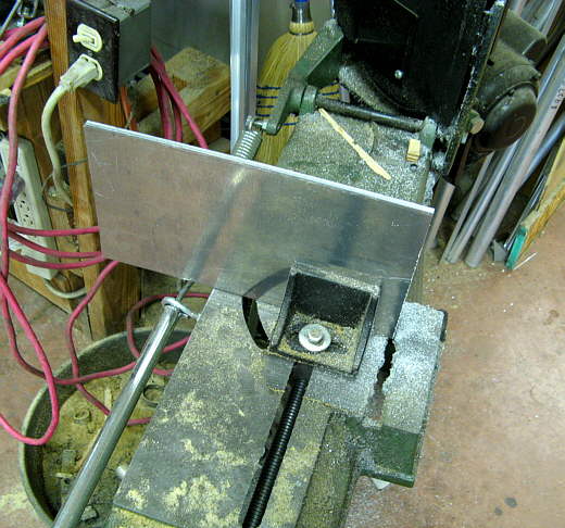
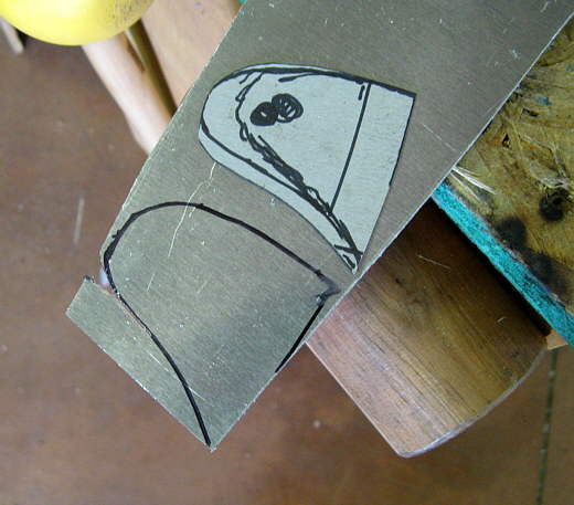
First a bracket was made to attach to the stern just to the port side of the rudder and to the starboard of the motor well. I forgot I had some thicker strap, so I found a piece of scrape aluminum and cut off a piece 1 inch wide.
...............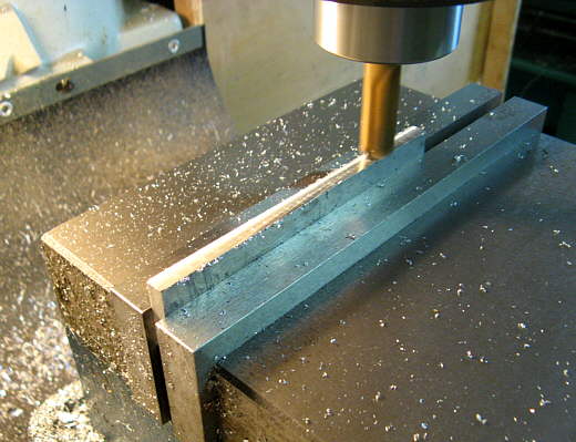
The mill was use to true up the edges along the saw cut.
...............
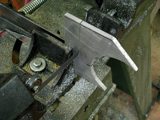
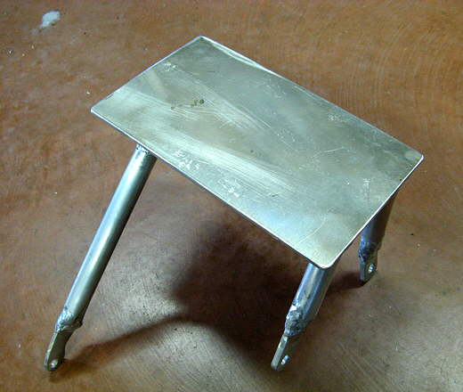
It was then bent in a vise and trial fitted on the back of the boat. Here the upper leg is still long and needs to be cut off.
...............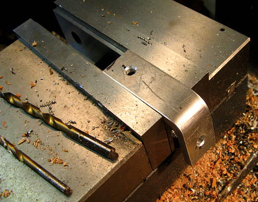
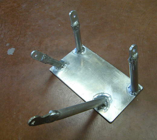
It was cut to length and holes drilled to mount it to the boat.
...............
Using the holes and a cut off bolt it was put in a rotary table on the mill and the ends rounded off.
...............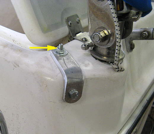
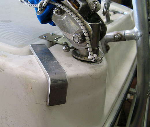
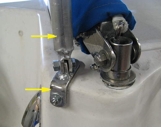
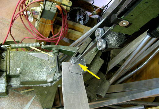
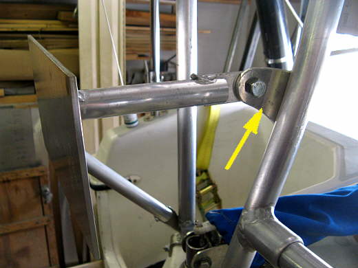
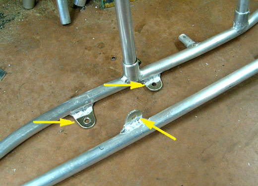
Here it has been attached to the stern. The bolts will be replaced with stainless ones and the one the arrow is pointing at will be reversed so that the head is on top.
The bracket was made to hold an upright stanchion that will go past the top of the pushpit. The stanchion will serve as part of the outboard support system and will also hold the mast when the boat is on the trailer and also be part of a hoist system to be able to lower the Nissan onto the Zodiac or to lift the Honda on and off the boat or to replace it with the Nissan if it fails.
...............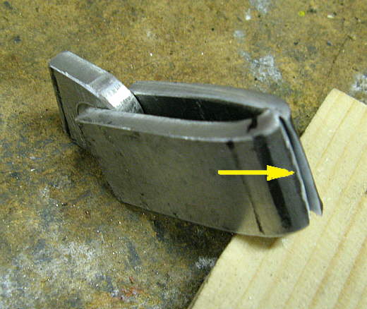
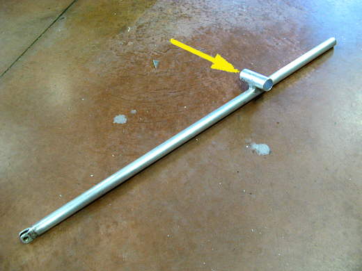
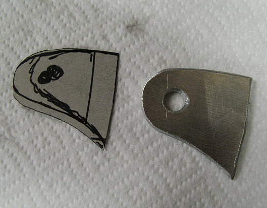
The left piece in the picture above will go on the bracket that was made above the the right piece will go on the bottom of the stanchion. While bending the right piece into a "U" shape it cracked (arrow) as it isn't really the grade of aluminum that you usually use for bending, but was what I had.
...............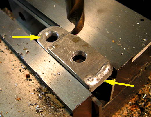
I welded up the crack and drilled a hole through the "U" shaped piece (right arrow). The other piece (left arrow) is just wedged into the "U" piece while I drilled the hole to hold it apart.
...............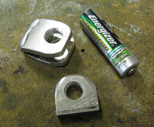
Here are the two pieces. You can see by the AA battery they aren't too large.
...............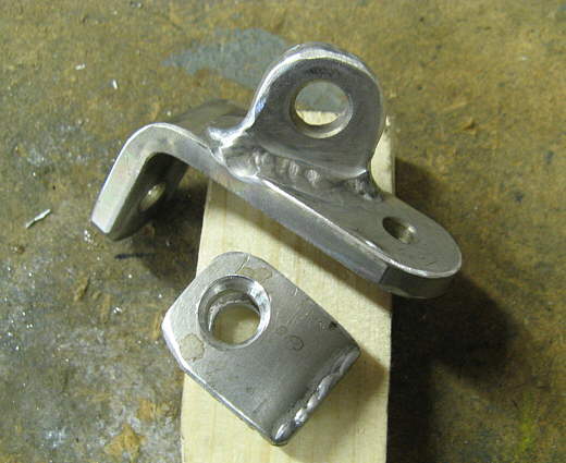
The one piece was welded to the bracket that had been made above.
...............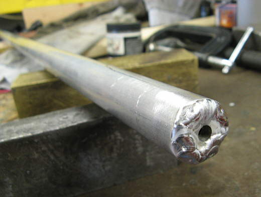
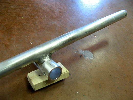
The stanchion was welded closed on the bottom end. The 1/4 inch hole was from when I had the piece that was welded to the bottom in the lathe where is was turned to the same diameter as the tube.
...............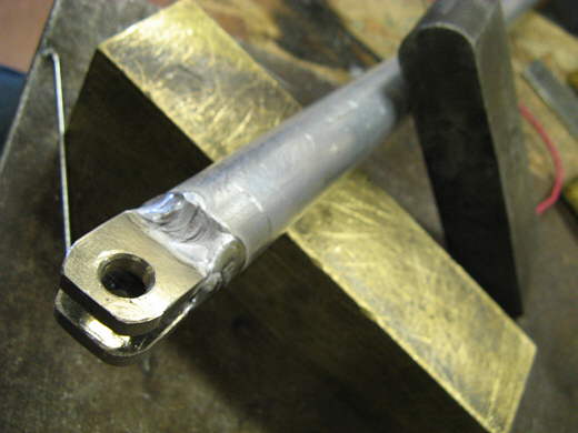
After the bottom was welded the "U' shaped piece was welded also to the bottom of the stanchion.
...............
Here everything made to this point is attached to the stern.
...............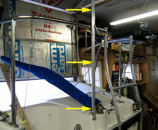
This picture shows the stanchion in place going up past the pushpit. As mentioned it will server three purposes.
...............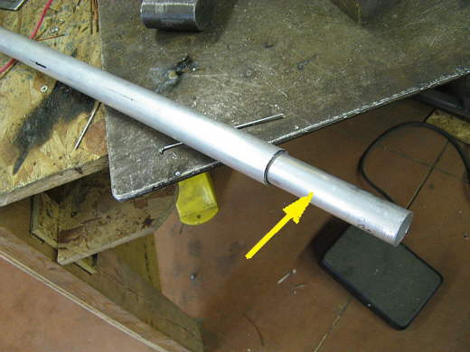
It is 1 inch tubing and a piece of the next size smaller tubing was cut to the same length and slid into it to reinforce it.
...............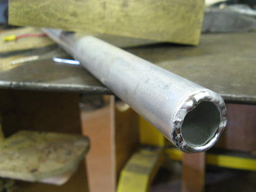
The two tubes were welded together at the top end.
...............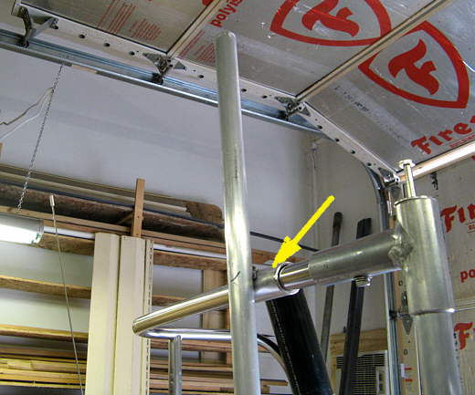
In order to attach it to the pushpit a sleeve was made (arrow).
...............
The sleeve was welded..............
...............
......... to the stanchion.
...............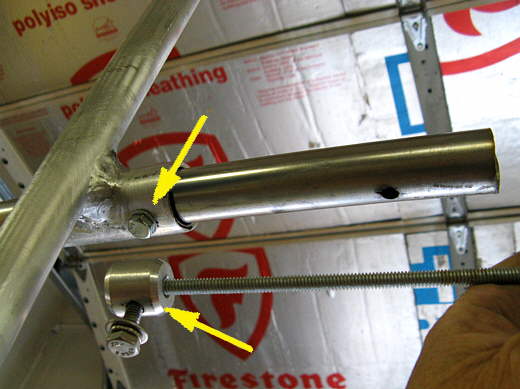
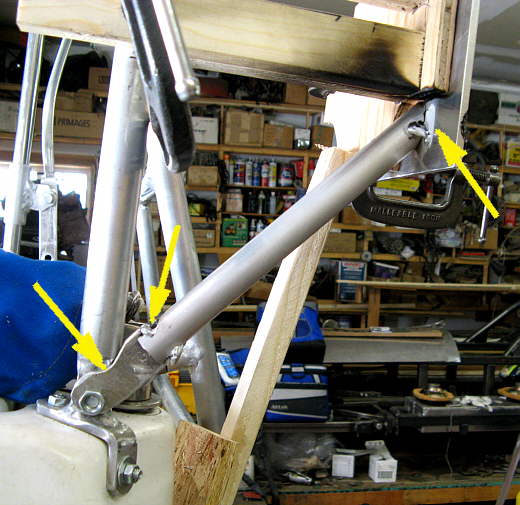
I used a bushing (lower arrow) that was slid into the pushpit tube with the threaded rod over to where a bolt (upper) arrow goes through the sleeve and pushpit tube and screws into the bushing. For more on how the bushings were made go ( HERE ) as I used them when I made the back swim/boarding ladder extension.
...............
The motor mount was to be attached to the ladder on the right side and the new stanchion on the left. First a plate was cut from some scrap aluminum for the mount. Also a piece of 2 X 6 will be attached to this plate and the outboard will clamp to the plate/2X6 combination.
...............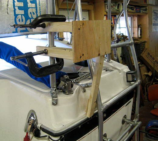
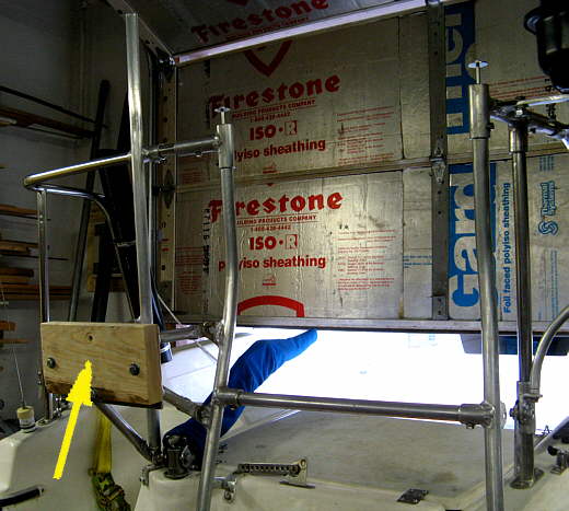
A simple wood support system was screwed together to hold the plate where I wanted it.
...............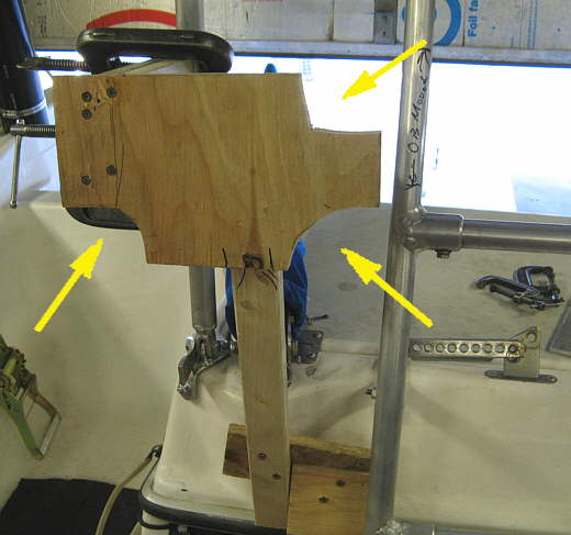
A couple corners were cut out so that supports could be run to the back of the plate.
...............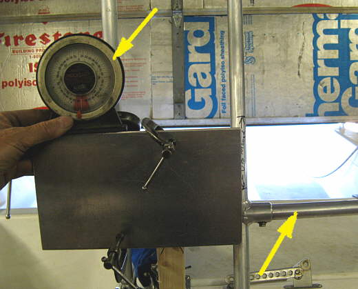
The plate was set at the same horizontal angle as the ladder. It is hard to find something that is level on the boat especially when the trailer isn't level. I referenced most of my leveling off the top and bottom of the companion way going down into the cabin. When I put the ladder on I felt I had it pretty level, so knew I needed to level this plate to the same angle as the ladder rung (right arrow) since the boat wasn't sitting level on the trailer.
...............
Four tabs had to be made to hold the plate supports to the ladder and the bottom stanchion bracket. I made a cardboard cut out the shape I wanted and transferred it to some scrape aluminum......
...............
...........and cut the pieces out with the band saw. This is one of the cheap $150-$200 band saws that Harbor Freight and Enco and others sell and works well for me as long as I don't push it.
...............
Here is one almost completed bracket.
...............
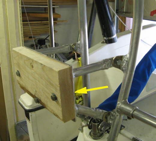
That one had to be modified a little (left bottom arrow) to clear the stanchion. It slides into a slit in the aluminum tubing (middle arrow) and tacked. The tube was tacked to the plate (top right arrow).
...............
Here you can see how another bracket was welded to the side of the ladder. Once these two were in place and the plate was stable I was able to remove the wood support system and weld the other two supports to the plate.
...............
During the welding process clamps were used to hold the pieces in place until they were tacked together with the TIG.
...............
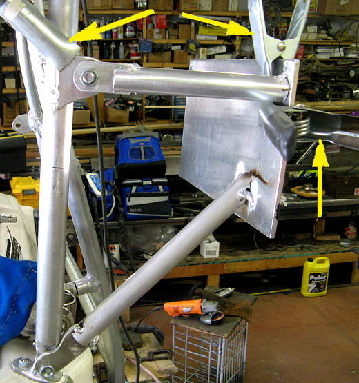
Here is the plate with...................
...............
.... the four support pieces welded to it. Also the tabs were welded to the aluminum tubes and.....
...............
.........the tabs that had been tacked to the stanchion and ladder side were finished welded.
...............
Here the 2 X 6 has been bolted to the plate and ....
...............
.... it is ready for......................
...............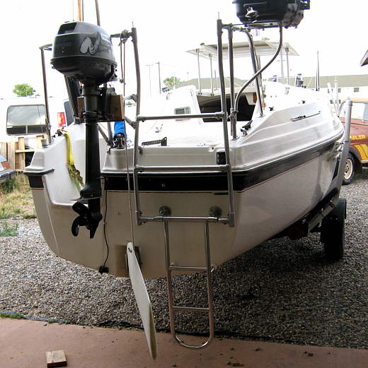
...........and outboard. Now the Nissan weighs about 60 lb. and the Honda weight about 100. To give it a test with the Nissan attached I also hung all my body weight (165 lbs.) on the mount and everything held fine. I'll keep an eye on it, but I feel it is plenty strong for the intended use.
...............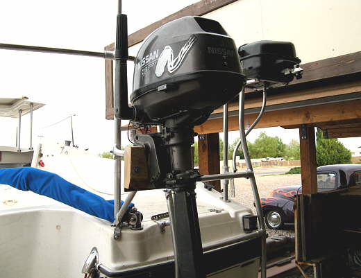
I've seen some outboards mounted higher, but wanted ours to be as low as possible for easy in getting it on and off and to make the construction of the hoist (coming up next) easier.
...............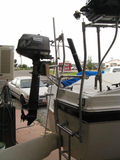
It also needed to clear the rudder when it was up. Both outboards do that. I'll mount the Honda later when I have some help or finish the hoist.
I know some of you will be critical of this as you wouldn't want the weight back here, but we will be cruisers and need to be as self sufficient as we can on the water and feel this is going to be a good mod for us. We like it already. Until I can get a second axle on the trailer and maybe even then we will carry the Nissan in the back of the Suburban to the water. It isn't hard lifting it onto this mount while the boat is on the trailer as the mount is very low.