................Previous Page....................................................... Next Page If There Is One
........--- Antenna and Mast for Bullet 2HP Radio ---
The last ingredient other than the router/computer that will receive the Wi-Fi signal is a mast for the antenna/Bullet 2HP combination and that is what this build page is all about. People who sell all of the above in a package deal and others tend to recommend getting the antenna about 12 feet off the water. It might be tempting to put the antenna at the top of the mast, but if you are in a marina you might be too high and might be trying to receive a signal that is broadcasting lower.
You pick an antenna based on dbi mainly and you would think you would want as high a dbi as you could find. The problem there is that the antenna is receiving and sending in a cone/beam or angle of reception. The higher the dbi and the smaller/narrower this angle gets. If the cone is real narrow and the boat rocks it will be trying to receive a signal from high above or lower than the available radio that you are trying to send and receive from at that Wi-Fi hot spot. In a building you could aim far away at a fixed know Wi-Fi location with a narrow beam. So with that in mind it seems that most people on boats use an 8 dbi antenna as a good compromise.
So on this page I'll be building a mast that will swing down while on the trailer or the water if needed and when it is up the antenna and Bullet 2HP will be about 12 feet off the water. It will go up or down in less than a minute using a swivel base and pinned supports.
.........
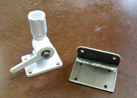
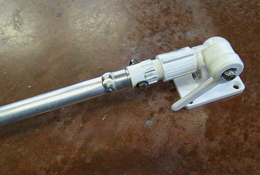
I bought the swivel mast mount on the left and made the aluminum bracket on the right from two pieces of strap.
.........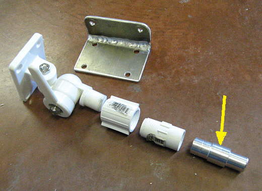
I got the middle fittings from the hardware store and machined the fitting on the right to go into the PVC fitting to its left and into.....
.........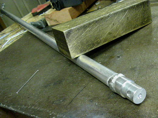
....the aluminum tubing above that is the mast. I welded the two together and then...
.........
... made a mount for the other end of the mast where the Bullet and antenna will mount.
.........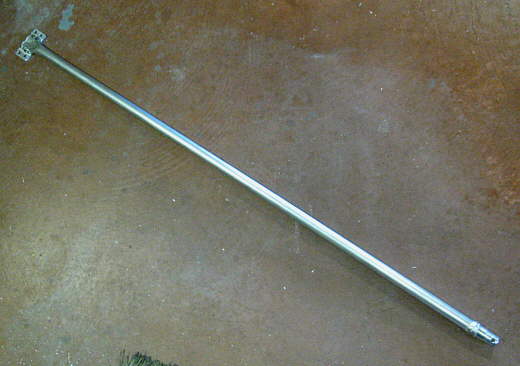
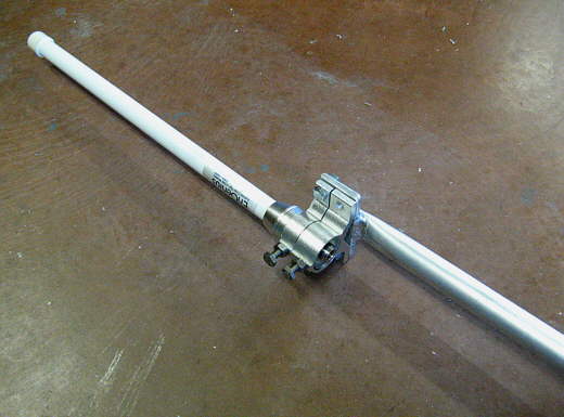
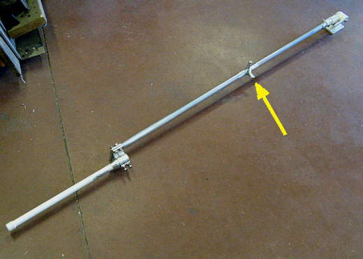
Here is the completed mast and it is about 5 feet long. It will be mounted to the solar panel array that is above the stern and from the water to the top of this mast is about 12 feet.
.........
The mast is pinned to the PVC fitting with a bolt, so it will come out if needed. The mount has a locking handle on the front that will lock the mast at different angles. We are just interested in this angle and 90 degrees from this angle.
.........
Here is the Engenius 8 dbi antenna with the mounts that came with it.
.........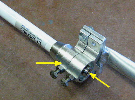
I modified the mounts some, but cutting the top one (left arrow) down narrower than the other one. I did this so that the threads at the bottom of the antenna (right arrow) are accessible to screw on the Bullet 2HP.
.........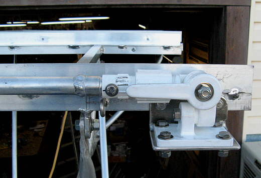
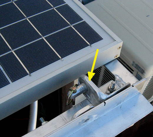
The swivel mount and its bracket have been bolted to the framework that holds the solar panels (the panels are not in place when the picture was taken).
.........
When the antenna hinges down it is captured by the bracket that the arrow is pointing to and then a pin is inserted to keep it there going down the road.
.........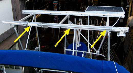
Notice that the antenna/mast are sized length wise to fit across the solar array. The 40 watt panel is in place, but the 60 and 80 are not in place for the picture.
With the antenna rotated up there was just too much sway in it and I didn't think the mount would last. Also there was a small amount of flex to the mount I had made.
.........
To fix the flex I added the side pieces.
.........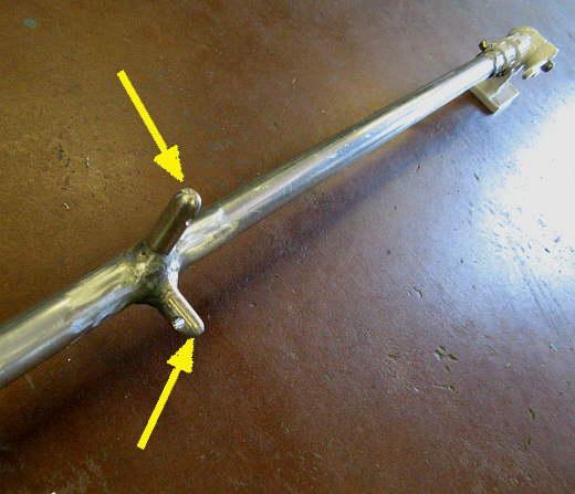
To fix the sway in the antenna/mast I added these two attach points part way up the mast for a fore/aft support and a side to side support.
.........
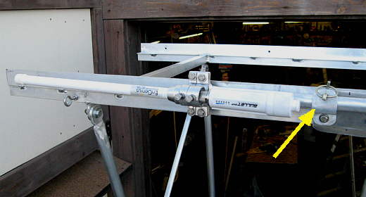
Supports will be pinned to the two ears (arrow).
.........
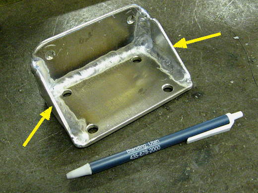
The bracket above was made and installed between the 40 watt panel and the other two panels for the fore/aft support to pin to.
.........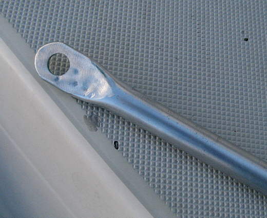
The support tubing is aluminum with the ends hammered flat and drilled.
.........
Above are the two support tubes with attached pins so that they can be pinned quickly to the mast once it has been swung up.
.........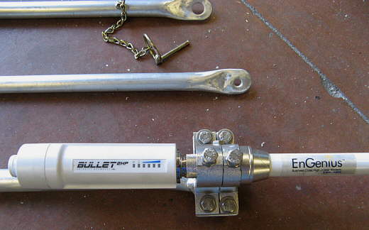
The two support rods, the Bullet 2HP radio and the Engenius 8 dbi antenna.
.........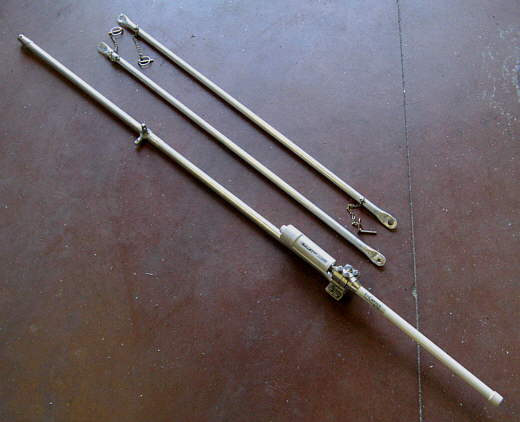
The components minus the mounting points on the solar array.
.........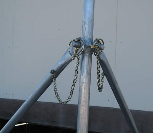
Close-up of how the supports pin to the mast. One of the supports unpins at the base and stays attached to the mast when it is swung down. The other has to be stored separately.
.........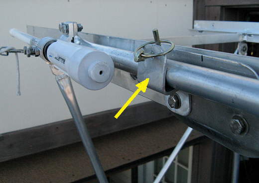
A close-up of the bracket that holds the mast towards the Bullet when it is in the down position.
.........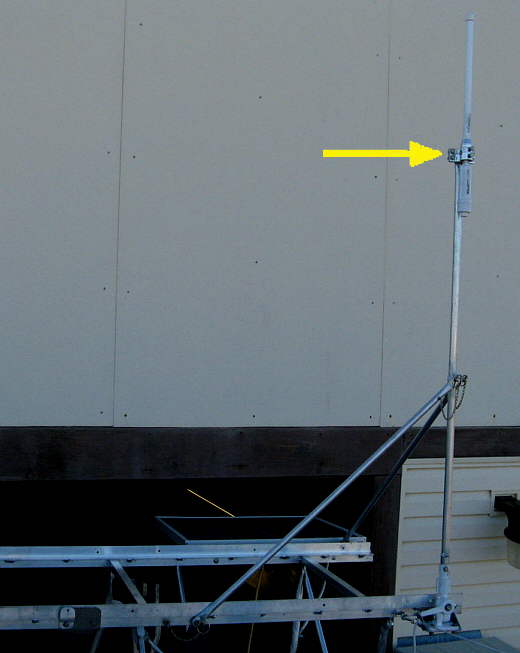
The mast raised. With the supports it is very steady and we will probably just leave it up most of the time on the water.
.........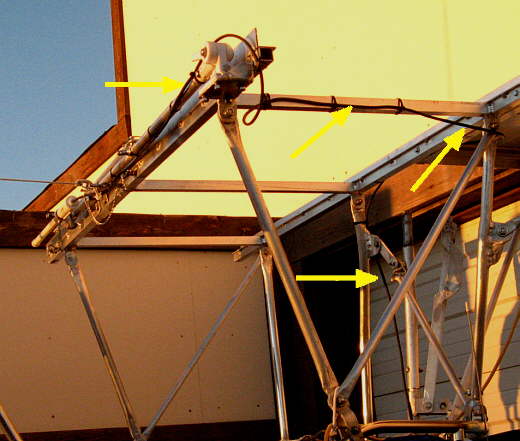
The ethernet cable runs back along the solar array framework (top arrows) and then down (bottom arrow) to the outboard well. I had started to use zip ties in the picture above and then remembered that I had to pull this framework off to get the boat in the other side of the shop to paint the bottom, so quit tying it down.
.........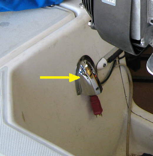
Once in the outboard well the cable goes through the vent (arrow) into the lazarette and then forward between the hull and the liner up by the rub-rail to the computer area.
.........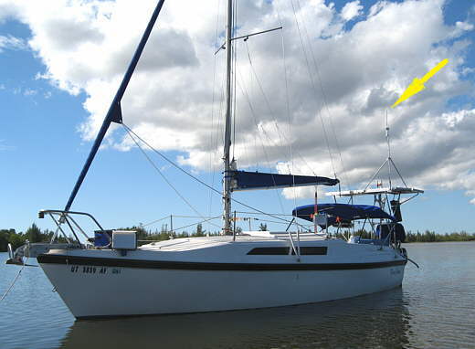
Above is a picture of the Bullet 2HP radio and antenna above the solar panels on the trip to Florida 2011-2012.