...Return To Mine & Other Bonneville Car Construction Pages
.Previous Page...............B'ville Car Index Page.........................Next Page
........................................... Rear Frame - Part III
............................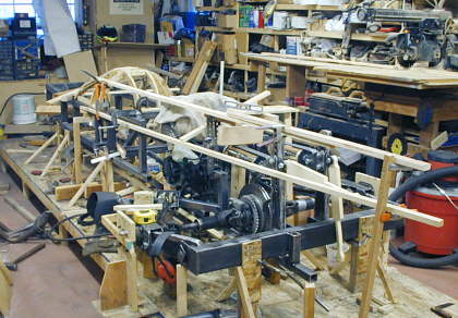
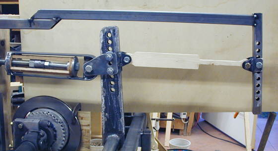
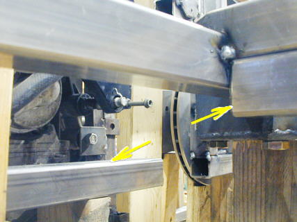
After completing most of the bottom left rear frame rail I started on the top left frame rail working from the cage back. Here I've located some stringers to help me visualize where the body will be so that I make sure all of the frame is inside of the body. Also of importance in this picture is the radial arm saw up in the right hand corner. Building the car to this point I have probably used it more than any other tool I have. It is invaluable in laying out parts (the numerous supports I have in place) and making wood patterns (see bottom of this page). Get one or at least a small compound power miter saw (Harbor Freight) has these pretty cheap and I built my whole house with one that cost $100.
............................. .
.
In this view you can get some idea of how the cars sides will curve from the nose to the cockpit and then back to the tail. For about 4 feet along the cockpit the sides will be parallel to each other the same distance apart. In front of the cockpit the sides will be gently curving out from the nose to the cockpit and behind the cockpit they will be gently curving in towards each other back to the tail of the car.
............................ .
.
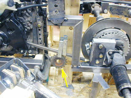
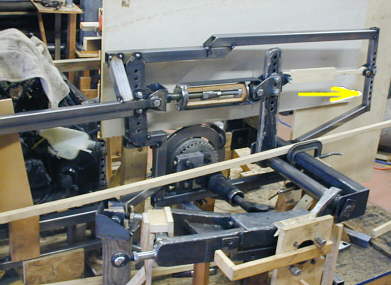
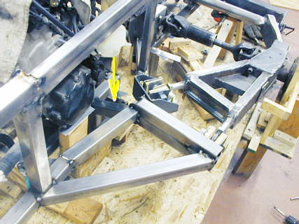
After finishing the bottom frame I realized it might be hard to mount my idler/adjustment sprocket for the chain (yellow arrow). I had to come back in and cut the frame out in that area. After I make the idler sprocket and figure out how I'm going to mount it so that it is adjustable I'll come back in and jog the frame around it.
............................ .
.
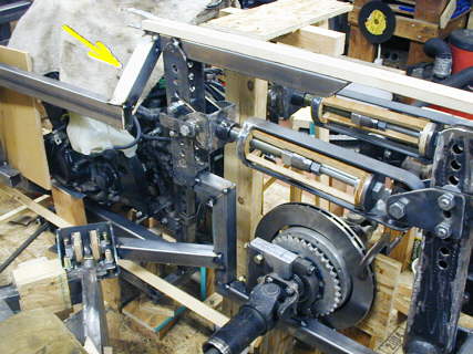
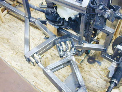
Next I came off the bottom rail with a support up to the bottom bracket that has the adjustment holes in it for the spring assembly. Note that I moved it back closer to the pillow block from the previous page. This was also to gain room for the idler sprocket. I will still put a short horizontal piece in between the vertical upright and the left side of the bracket that holds the pillow box. Also you can see here where the frame branches off to the A-arm support on the left side of the picture. The arrow shows how I have brought the top frame rail from the cage back to this area.
................ .
.
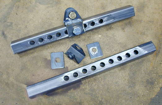
These are brackets to mount the end of the shocks at the extreme rear of the car. I drilled them with holes 1 inch apart to provide shock adjustment. The two black brackets are shock mounting brackets you can buy. I welded two ears on them that allow the bracket to slide up and down on the square tubing and be located with a 1/2 inch bolt.
........... .
.
The top frame rail was extended back far enough to mount the piece I made in the previous picture. It still needs adjustment here as the holes are not parallel in the rear bracket with the holes in the lever arm. Since the lever arm is at a slight angle the rear bracket needs to be at the same angle. That also held true for the bracket that supports the left side of the spring assembly.
............................... .
.
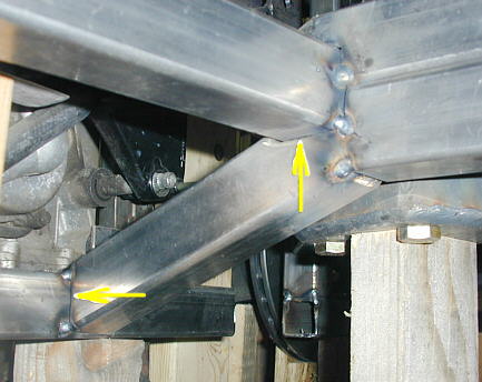
Here the rear shock bracket is in place (arrow) along with a diagonal that goes at an angle down to the rear cross-member. There will be more bracing in all of this after I finish the rear frame on the right side of the car. The long thin board resting on the rear cross-member represents the curvature of the body.
.......................... .
.
Next came pieces to locate and support the A-arm pivot points. The pieces of particle board on each side of the heim joints will be replace with shims later. You can also see I've added a vertical piece between the top and bottom frame rails to the right of the adjustable A-arm mounting pad. This area will get diagonal bracing as will the whole length of the side of the frame between the top and bottom rails.
........................... .
.
I also inserted (see arrow) another short piece to tie this area into the very bottom frame rail. Below I will show how I made this piece. The very bottom frame rail barely visible under the motor will add rigidity to this portion and also provide for a bottom motor mount. After I get the idler sprocket figured out it will tie back into the rear part of the frame.
............................ .
.
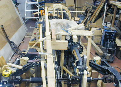
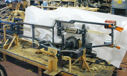
This gives you an overall view of the left side frame at this point of construction The two coffee cans represent the two chute tubes. There will be a vertically adjustable horizontal bar between them that the chutes will attach to. I don't need a chute to begin with as the record in my class is under 175 mph, but want two tubes in case this car with a different motor ever gets into the 200's and I feel the need for a reserve chute. Tom Burkland suggested that it was easier to design the car from the beginning for two chutes than to have to adapt to it later. Good point and I'm going to follow up on it.
............................... .
.
Here is the cut-out board (to the right) that I have shown before. It represents the thickness of the side pods on the car that will cover axles, suspension and locator parts. I have it here to show clearance on the A-arm support that comes out the side of the frame......
................................. .
.
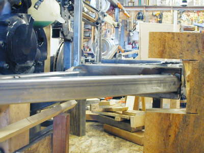
.........and here it shows the clearance on the rear crossmember. The gap is 5 inches tall.
............................. .
.
Now the rest of this page is how I make some of my frame parts and might not be of much interest, but I'll put it in as it might help someone someday. There isn't much of my frame that is straight, so I end up with a lot of angled cuts and some compound angle cuts that I have to make. Above I wanted a short 8 inch or so piece to go from the very bottom frame rail up to the support going out to the A-arm. This was a tight location to work in.
................................ .
.
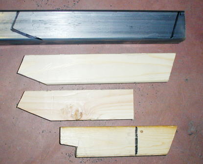
I started by cutting the two bottom pieces you see here. I would hold a piece of 1 X 2 at the angle I wanted and then lay another piece on the frame and scribe lines parallel to the frame both vertically and horizontally. Then I cut the angles on the radial arm saw or my band saw. This piece was so short it was easier to cut one end on one 1 X 2 and the other end on the 2nd 1 X 2 (the two bottom pieces). Then I held the two pieces together and slid them until they contacted both of the frame rails. At that point I made the black mark on the bottom one. This gave me the finished length. I transferred the angles and length from the two pieces then to the center piece and cut it out and tried it for fit. It fit good, but besides the shown angles there was a slight compound angle as this new piece didn't intersect the rails at a true 90 degrees. So I laid the wood pattern on the steel and marked it about 1/4 inch long, so I could grind to fit. This sounds complicated, but only took about 5 minutes (about the time it took me to type this).
................................ .
.
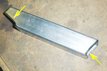
Here is the piece after cutting to rough shape with the chop saw and then grinding on it for about 15 minutes and trial fitting it. Besides the compound angles I also had to notch it (arrows) a little on both ends for it to fit in against the frame rails. This worked the first time and probably wouldn't of if I would have just tried to take measurements and cut it. The neat thing about this is I never used my tape measure once.
.............................. .
.
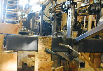
Here the piece is tacked into place and you can see the purpose of the notches in the previous picture. I use pieces of 1 X 2 to make patterns for most of the frame pieces and it goes really fast that way. There are probably lots of other methods also.
..................................................................Next Page