...Return To Mine & Other Bonneville Car Construction Pages
.Previous Page...............B'ville Car Index Page.........................Next Page
...............................-- Intake/Exhaust/Tail Part I --.................
.................. .
.
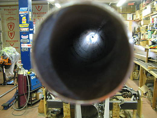
Are we looking to see if there is any light at the end of this project? Actually this piece of .......
.................. .
.
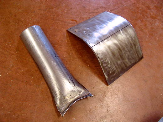
.......... 2 inch exhaust tubing is the foundation for the intake track, the exhaust system and a tail like section that will run for 12 feet (the length of the tubing) from the back of the cockpit to the very rear of the car above the chute doors.
.................. .
.
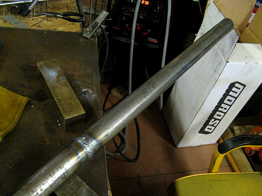
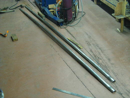
Since I had a 10 fool long piece if had to weld a couple more feet onto the end of it. Next ..................
.................. .
.
......... I cut it as close down the middle as I could with the plasma cutter. One piece will be the top of the intake/exhaust/tail and the other will be the bottom.
.................. .
.
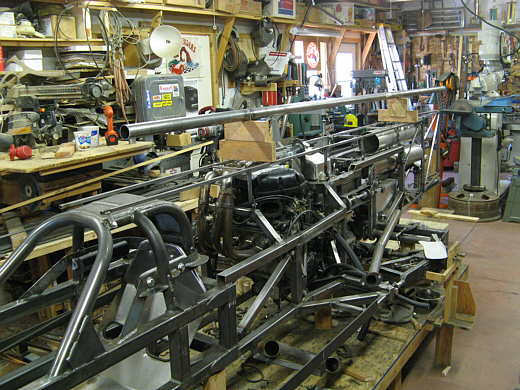
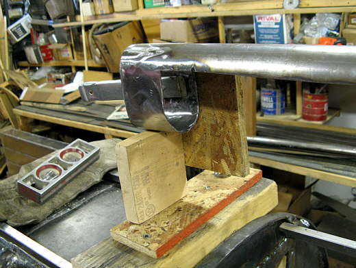
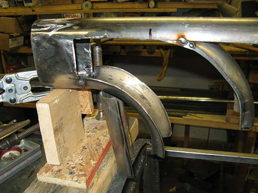
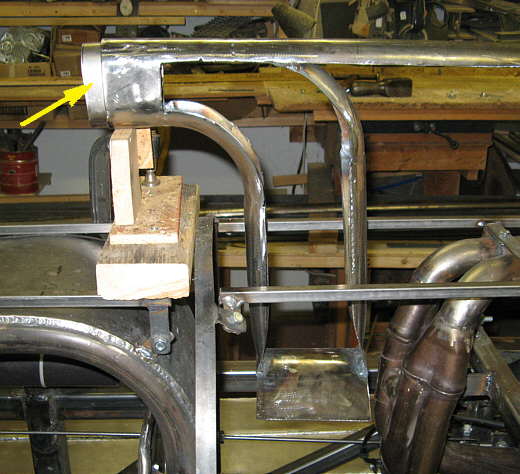
I blocked what will be the upper halve in place the distance above the car that I want it to be. You can see the firewall. under it here and that is the top of the main body. I started to form the intake opening with a section of the bottom piece and two pieces of 16 gauge (.063) steel for the sides. Using the scoop formula on my site ( HERE ) I determined what I hope will be the right size opening for the 750 motor. When I go with the larger motor and hopefully faster the opening can actually get smaller. To do this I'll have different sized extensions that will fit onto the front of what we see here.
.................. .
.
I welded those pieces together and ground the welds flush.
.................. .
.
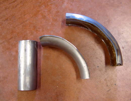
Next I took these pieces I had laying around and .......
.................. .
.
............... cut them in half. They were then.......
.................. .
.
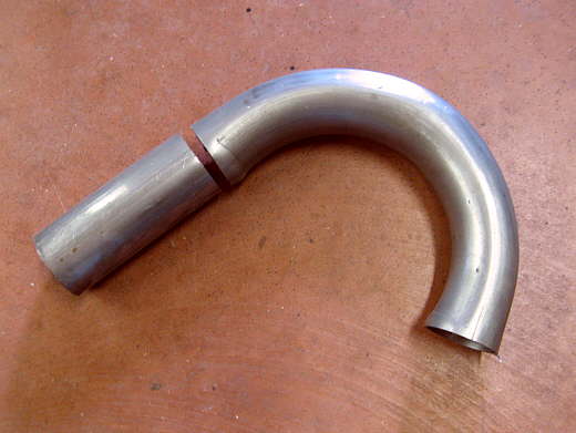
........... welded in to start the intake track down into the engine compartment. Notice how the volume of the track is getting larger.
.................. .
.
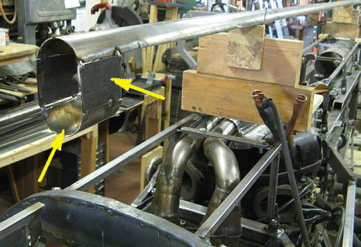
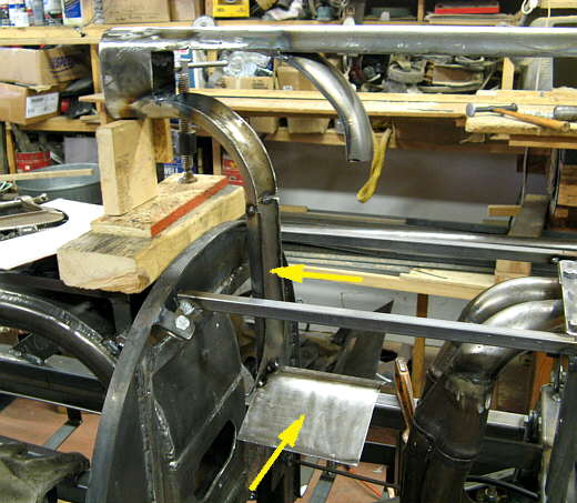
These pieces were then made out of the tubing above and some flat 16 gauge steel to start the plenum area that the....
.................. .
.
......... intake air will flow into. This is a pre-plenum and from it the air will flow to the air box shown back on page 112. Later this plenum will feed to the turbo when I have a turbo motor. The arrows point to where the two new pieces were welded into position.
.................. .
.
Next another back piece was added.
.................. .
.
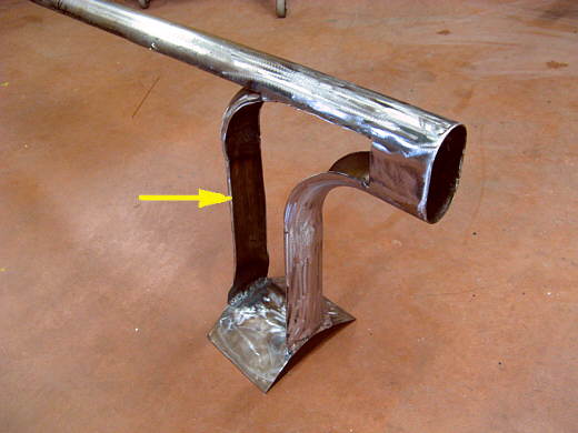
The arrow points to the piece that was made that just slides into the front of the inlet. An inlet of the size of my choosing will be welded to it and then that whole assembly can slide into the front of the inlet track and be changed if it doesn't work out.
..............................................................Next
Page