...Return To Mine & Other Bonneville Car Construction Pages
.Previous Page...............B'ville Car Index Page.........................Next Page
..........................................-- Side Head Restraints --
Ever since Tom Burkland sent me his thoughts on safety .I've wanted to limit my head movement in the cage to no more than about 1/2 inch in any direction if possible. Presently, starting in 2008 SCTA requires no more than 2 inches of lateral head movement on each side. I wanted it to be much less than that so on this page I'll show you how I made some adjustable side head restraints.
.................. .
.
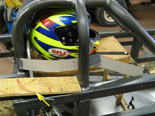
I started with some cardboard templates for the side pieces that the restraints will be attached to. I had to angle the front part down to comply with the 120 deg. of vision rule. The arrow points to the curve I wanted in the piece that comes from the back to the middle hoop.
.................. .
.
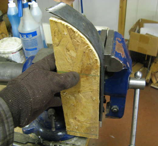
I cut a piece of 1/8 inch by 2 inch strap to the length of the pattern then using the cutout curve on the particle board as a template I bent a rough curve in the strap using the vise and a hammer. I just kept moving the piece in the vise and hit it a few times and move it again and repeated this until I had the shape I wanted. Then I trial fitted it to the car and adjusted as necessary.
.................. .
.
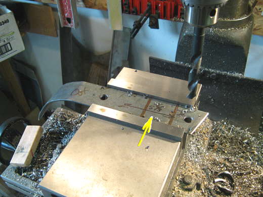
I drilled two 1/2 inch holes in the piece 5 5/8 inches apart. One nice thing about the mill-drill is the accuracy of drilling hole so pieces fit together time and again. Each full turn of the handle on the table is .125 (1/8) inches. So in this case locate the first hole and drill it. Zero the scale on the table handle and then turn it 45 turns and you have exactly 5 5/8 inches to with-in a thousands or so. I also got a 17/32 ( 1/32 over 1/2 inch) bit from Enco and use it for my 1/2 inch holes. This gives some clearance for paint or powder-coat.
.................. .
.
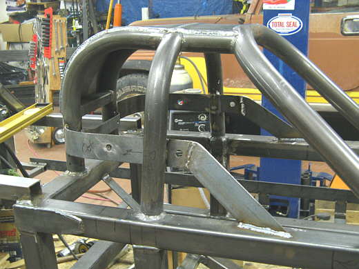
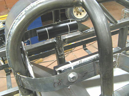
Here I've tacked the strap in place along with the diagonal piece made also from 1/8 by 2 inch strap. I put this piece in a location that would end up with the side restraints about ear level on my helmet. Here are Tom's comments that led me to using this position:
"Even though the rounded shape of the cage will restrict lateral helmet
movement, you should still
be building in a dedicated lateral pad set that will contact the helmet on the sides outboard of
your ears (directly at the height of the CG of your head with the helmet on to prevent neck
bending moments). The top contact in rounded cage structures creates a down load that adds
compressive load to your neck, which is already rotated quite far forward in a lay down seating
position like yours. This rotation compresses the discs between the front of each vertebrae and
reduces the ability of your neck to safely absorb any more compressive load without serious
injury. Be careful that these pads do not restrict your shoulder movement during exit actions. If
you can avoid having to roll your shoulders sideways to fit between the helmet pads it will greatly
simplify the driver contortions required to get in and out of the car. This is especially critical if
you are injured and the EMTs are extracting you without a full diagnosis of the extent of your
injuries."
Good thoughts, thanks Tom. I want to remind everyone that many of Tom's thoughts and suggestions are directly related to my construction and cockpit geometry so they may not be correct for another application. So, before you follow these ideas or any others that you find on this site make sure they fit your application.
Also I never thought about it but since your equilibrium is associated with your ears, I think, it would make sense that they are located at the CG of your head. I wonder if that is right, well on to the restraints.
.................. .
.
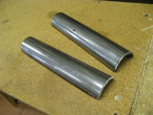
A piece of roll bar tubing 8 inches long was cut in half with the plasma cutter next.
.................. .
.
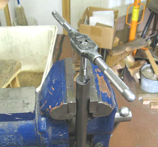
I needed 4 threaded bushings. I took some 7/8 inch round stock and drilled it out with the lathe to a little over 2 inches deep. Then I would tap it about 5/8 of an inch deep at a time and cut 1/2 inch off the end. Then tap some more and cut another 1/2 inch off until I had 4 bushings tapped for 1/2 inch coarse bolts that where 1/2 inch tall.
.................. .
.
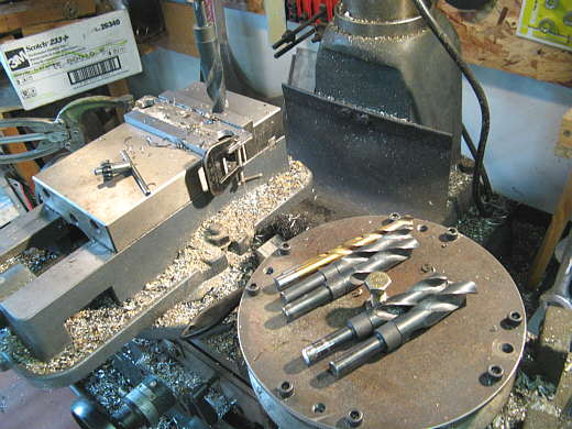
Next two plates were made, also 8 inches long to weld to the back side of the roll bar tubing I had cut. Two 7/8 inch holes were drilled in them exactly 5 5/8 inches apart, see where we are going with this. I know a lot of people don't do this, but I drill the holes in steps. The reason I showed the bits in this picture. I start with a centering bit (not shown) and drill a small centering hole, in this case two 5 5/8 inches apart. Then I go with a 1/4 inch bit, since I can get them cheap in 10 packs. Then changing speeds I go to the other nitrate coated bit a couple sizes un 1/2 inch. Then in this case the 5/8, 11/16, 3/4, 13/16 and finally the 7/8 inch bit. It just takes a second to change them and they last much longer, at least for me. When I get to the 5/8 inch I also go down one more gear. The mill-drill I use has 6 speeds and you just flit one or two levers to change speeds in the gear box. Simple and nice. I've had to drill hundreds of holes on this car so far.
.................. .
.
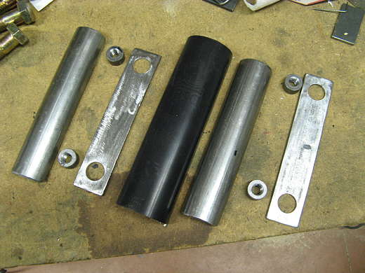
Now we have the components for the restraints, 2 pieces of tubing cut in half, 4 threaded bushings, 2 plates with holes for the bushings that will be welded to the pipe and two pieces of roll bar padding (only one show in the middle).
.................. .
.
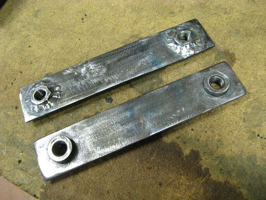
The bushings were inserted 1/2 way through the plates and welded on the back side only.
.................. .
.
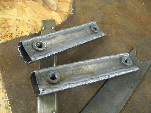
Then the plates with the bushings in them were welded to the pieces of pipe.
.................. .
.
At this point the restraint support pieces where finish welded. Also notice that before I did this I had a day earlier finish welded the cage to the frame members.
.................. .
.
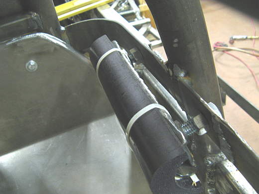
The roll bar padding was attached to the 1/2 round tubing pieces and they were bolted to the side of the supports that have the hole in them 5 5/8 inches apart.
.................. .
.
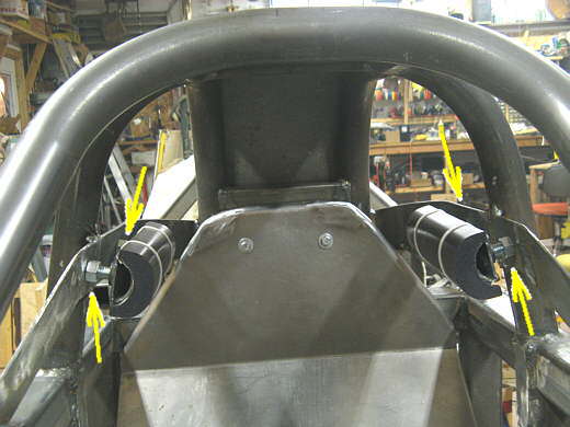
They are adjusted by loosening the jam nuts (see arrows). Then the 1/2 inch bolts can be turned which moves the support in or out. The fronts and backs can be adjusted differently to change the angle also. Once you have them where you want them you lock the jam nuts back down. I did this in case I ran into different width helmets in the future. The helmet I'm using for all of this was given to me and doesn't meet the rule requirements. I need to get one soon.
.................. .
.
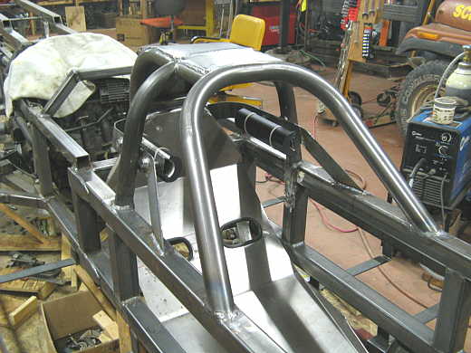
Another view.
.................. .
.
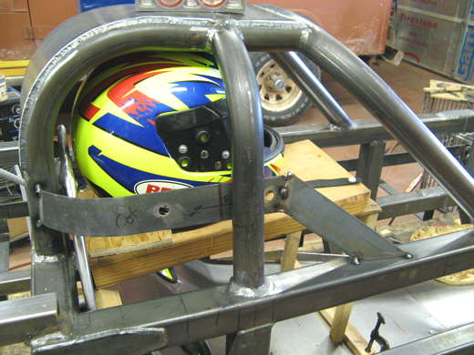
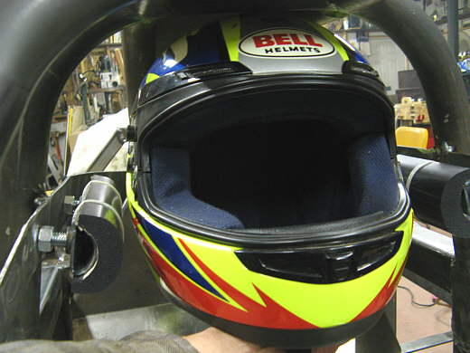
This shows the helmet in place with a little less than 1/2 inch per side movement available.
.................. .
.
Well another build day and a little more progress.
Next gussets still have to be added to the cage hoops to tie them into the frame rails. I wanted to finish the items inside of them first though since they would have been in the way a little.
..............................................................Next Page