......................................Return to Sumner's Home Page
.....Return To Mine & Other Bonneville Car Construction Pages
.............................--- Notes from Tom Burkland ---
........................................( Links to the Burkland Family's Bonneville History )
Please note that Tom had been sharing some very good ideas about LSR cars with me and has agreed to let me share them with you. Some of his comments are answers to specific questions I had to him, so if you don't quite understand the context let me know.
I would like to include the following quote from him:
"First off, you may use any of my comments in further distribution
to the many interested folks in the LSR community. Many of them come from practical experience, we've even unintentionally
crash tested some of these features, and others were developed as a result of the streamliners incident in 2001.
Much of the cockpit design detail comes from many years of fighter aircraft experience, crash investigation, and
ejection seat testing. Remember that the actual application to your, or anyone else's project may be different
than the exact configuration suggested."
Suggestions on driver compartment (cage):
There are a few suggestions I would make so they don't get left until the end of the project when corrective
actions are much more difficult.
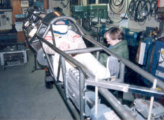
-First the incline angle of the front hoop on the cage will make exit from the cockpit more difficult, unless the
foot box is long enough to allow you to slide down and forward in the car enough to get your head rotated out from
under the cage. Your head will rotate from the top of your shoulders and increase the effective vertical height
required to fit under the cage during entry and exit. It will be much easier to get down into the car than to lift
yourself back up and out, so make sure there is enough room for this to happen.
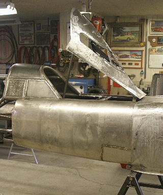
-Consider the arm/limb restraint early in the cockpit design process to provide the proper protection for these
precious parts. Our car has a combined canopy, steering, and instrument panel that lift up for egress. This is
great from a practical standpoint, but not so good for effective arm restraint application. It also is quite a
bit taller than your concept so the driver is not reclined as much. The ideal situation is very short arm restraints
(possibly tied directly to the steering wheel) to limit the amount of potential movement and resulting injury.
Your control layout needs to take this into consideration since the locations of all the controls must be very
compact to make this functional.
-Think about access to the cage for removal by the emergency response crew. The jaws of life need to be able to
get around the base of the tubes to cut them loose if required. Our second cage is fully plated to the chassis
making this very difficult. It is a much stronger construction with the full shear plates on the outside, but very
difficult to extract an injured driver from.
-Proper restraint of the helmet and head is very important to prevent neck and basal skull injuries. The basic
cage, with proper non resilient padding is very good at supporting the helmet laterally and rearward but leaves
the forward direction up to the tension capacity of your spine. Our solution was to add a bumper surface to the
canopy latch that prevents forward movement of the helmet (either from crash loads or the routine deployment of
parachutes) that moves up with the canopy for exit. This system provides about ¼ inch of free space for
the helmet in any direction to avoid chassis vibration but prevent neck extension type injuries. The same thing
could be accomplished with a separate removable member across the front hoop just above your eye line with pin
connections to swing it out of the way for exit purposes. It depends on what fits your overall cockpit configuration
best.
-Make sure you provide lateral support of your shoulders and hips to be comfortable with a side landing from high
altitude. As long as the helmet, shoulders, and hips are supported to maintain spinal alignment you can survive
very high G levels. Tight cockpits with little or no room to develop contact velocities between your body and the
hard surfaces are a benefit in walking away from incidents. The hard surfaces need to be flat and parallel to your
body surfaces to reduce contact injuries as well.
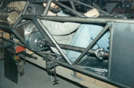
-With the highly reclined driving position you will want to look at the multi point crotch strap harness systems
to hold you up in the cage. The attach points for these harnesses are slightly different than the standard five
point and should be designed into the chassis structure.
Tom Burkland
................ 
................ 
...........................................................
More suggestions on driver compartment (cage):
Bob Stroud has supplied parachutes to our project for some time now and has plenty of good suggestions for
the special problems that come around a land speed car. He is a great resource for the entire racing community
to use in solving the really difficult problems. His catalog only lists 5 point harness systems. I would strongly
suggest you only consider a cam lock buckle and six point harness configuration in this lay down cockpit. Separate
shoulder belts mounted as close as possible to your seat plane are more stable and stiffer (less stretch to allow
you to move around during the incident). The traditional aircraft latch is very prone to getting released by the
flailing parts and has a much larger footprint against your body, which may be uncomfortable during the fold and
exit movement. The multi point formula car style harness can actually be pre-loaded without raising your voice
and distributes any downward loads generated during a crash over the correct parts of your anatomy.
These low cars are hard to get in and out of while still retaining good structural integrity. My crew jokes about
crumpling the driver up like a sheet of paper, throwing him in the car, and letting him flatten back out. You may
want to consider some non traditional forms of steering the car to eliminate some of the clutter above and in front
of you. Handlebar arrangements like the motorcycle streamliners reduce the height of the controls, or vertical
sticks on each side could eliminate the overhead hardware altogether. A net or cross member system over the top
of your arms/hands could meet the rule book requirement without arm restraint straps. This cross member would also
help the structural integrity of the forward section of the chassis and be moveable through a pin removal or latch
arrangement. Does your proposed foot box have room to extend your feet either between or outboard past the pedals
to get far enough down in the cockpit to limit the amount of neck bend required to exit the cage? You may be able
to move the canopy hinge location far enough forward to get your knees up through the top body line once the canopy
is unlatched and lifted. The Turbinator actually had a rolling seat pan, similar to a creeper on rails, which made
it much easier for the driver to slide forward for the required helmet clearance. Their cockpit was very wide so
the drivers knees could be spread laterally to decrease the length during this move. The lateral support I mentioned
in the first note was not provided for.
One of the solutions we considered was to have the top plate of the cage hinged and latched to allow the driver
to slide straight up through the space between the two cage hoops. We were not able to get enough vertical bending
strength in our chassis (195 inch wheelbase, 5000 lb. loaded weight, almost 2000 ft-lbs applied torsion) with the
cage plate un-welded, but your application will have much smaller loads to carry (shorter car, lighter weight,
and almost no torsion with the chain drive). This arrangement would probably still require a canopy or access hatch
of some sort for maintenance and crew assistance buckling you in the car. The latch and plate system would have
to be well thought out to guarantee structural integrity during the crash loading and still be un-latchable by
the driver for exit purposes.
Keep working out the problems in wood and cardboard before you spend the time and money to make real hardware and
your project will be a success.
Tom Burkland
................ 
Suggestions on CG and CP:
Just in case you start to get in a hurry and want to bypass some of the cockpit planning and safety equipment
selection check out this clip. The Rice-Vigeant site may have some other information you would be interested in
since their car configuration is very similar to what you have proposed. The other sites are other harness manufactures
that lists the formula style six point harness that would be a very good idea for your application. I'm sure Bob
Stroud would be willing to build this setup for you also, even though it is not listed in his catalog. Autopower
is Rick White's company in San Diego with lots of Bonneville experience from their 131 streamliner days.
http://www.ricevigeantracing.com/ricecrash.wmv
http://www.crowenterprizes.com/formula.html
http://www.impactraceproducts.com/item.wws?sku=50351111
http://www.autopowerindustries.com/Driver_Restraint_Systems.htm
The Rice lakester crash points out another design detail that needs to be addressed earlier rather than later.
Directional stability of the car must be positive for a comfortable safe ride. This means the CG must be ahead
of the aerodynamic center of pressure (CP) so the car will go straight on its own. Both the CG location and the
aerodynamic surfaces that determine the center of pressure are variable at this point in your design. Alan's crash
appears to have the car swapping directions prior to the rear axle failure and the flat rotation on the ground
as the car slides to a stop would indicate the CG and CP of this car were virtually the same point. With proper
directional stability designed into the car (both shape and balance contribute) you will be able to spin the tires
at speed with no change in direction. We have run all four tires on the streamliner over 130 mph faster than the
ground speed with no fishtailing or unpredictable movements because the shape is aerodynamically stable (this
generally hard on tires and not good practice!). Drivers can very carefully hold a neutral stable car in a straight
line, but an aerodynamically unstable car will eventually turn around and bite someone.
http://www.big-boys.com/articles/rx7.html
This is another clip of a vehicle with slightly negative directional stability. You'll notice the throttle is actually
closed before the car goes around but it continues to rotate anyway, even after it is upside down. Larger vertical
surfaces aft of the CG would move the CP farther aft to help this problem or more weight forward to move the CG
ahead.
Open wheeled cars are somewhat special as the air flows on both inside and outside surfaces of the wheels so these
must be accounted for in the aerodynamic design. Traditional Bonneville mentality adds ballast to the rear for
more traction which moves the CG aft and tends to destabilize the vehicle. Most cases have enough margin to shift
the CG without spinning, but if you are already close to the edge it may be too much. Properly balanced vehicles
will actually crab into cross winds with no driver input and continue going down the track at the small slip
angle. A 10 mph direct cross wind at 200 mph ground speed is 2.86 degrees of side slip with the steering still
dead center, so the driver will notice if he is paying attention.
http://www.plsthx.com/disp.php?type=m&id=96
This clip is included to convince you to avoid any flat surfaces on the bottom of the body shape. Typically the
lakesters have very low aspect ratios (narrow and long body shapes) so this is not too large a problem. We also
run on very flat surfaces (except for parachute failures and going over the crunchies and drag berms at the far
end of the track) so the initial nose up moment is not very common. Round surfaces to allow any pressure to bleed
laterally across the lower surface will avoid any of these flight activities.
Tom Burkland
I spent some time with Bob Stroud last weekend in Ohio, we were asked to do a little consulting with the
OSU folks on the follow on project to their electric streamliner. He does have a multi-point harness system that
will work in your car. His arrangement uses the cam lock latch I suggested in the previous note. (I bought the
7 point cam-lock from Bob--Sum) He is also your supplier of choice for all parachute needs in this custom application.
The sternum strap that Jack suggested is a fairly common thing in oval track and sprint car racing. If it is tight
enough to actually contribute to retaining you in the car the ability to expand your chest cavity and continue
breathing will be very restricted. Your rib cage is not a very robust area to be applying these types of high restraint
loads to without causing further injury. I would attempt to get the standard multi-point harness system correctly
located in the car and not worry about the other options.
The curved lower section (I went from straight across bottom cage members to dropped members--Sum) will actually
be a much better fit to your body. Make sure the lateral clearance on your hips is tight enough to keep the spine
straight during a lateral load. The shoulder clearance should be fairly tight on the upper rail as your model looks
at this point, make the lateral clearances on the helmet small as well. You may also want to get some dimensions
from a currently legal helmet before finalizing the cage size. The one you have in the photos is well out of date
and very thin compared to what you will use to actually pass tech with the car (I have since gotten a helmet with
larger outside dimensions to help with fit in the cage area--Sum).
Your lower body curve looks good from an aerodynamic viewpoint. Be careful as you add more lower surface to not
get lift forces.
Tom Burkland
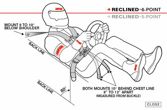
The new (in the 2005 rule book) seven point belt requirement for lay down cars is intended to provide better
down holding capability to the shoulder harnesses and prevent the driver from sliding up into the cage. The shoulder
harnesses really have two purposes in these lay down applications, first to hold your shoulders against the seat
back, and second to prevent you from closing the gap above your head and hurting your neck. The conventional below
the shoulder mounting position provides some downward component (to prevent sliding up), but is really only intended
to retain your shoulders back against the seat surface. The seventh crotch strap running straight down from your
chest line holds the entire harness down and greatly increases the shoulder harnesses ability to prevent your from
sliding up into the cage. This extra strap really does nothing to prevent submarining under the belt system as
this function is retained by the other two V oriented crotch straps. They can either be attached right back to
the lap belt attach points or separate locations of their own outboard of your hip width. Bob will gladly make
this belt set up for you if you have the dimensions, adjuster locations, direction of pull, and latch style in
mind. Be careful of the expiration date on the actual webbing, since the build cycle on many of these projects
is long enough for the belts to be expired prior to first actual race use.
The helmet purchase should also be delayed until closer to actual race use as they now have expiration dates as
well. Type and brand are personal preference, but the top line for fire protection has to be one of the integral
Nomex head sock configurations from either Simpson or Impact. Impacts new series even has an organic vapor filter
built into the chin protector to prevent nitro asphyxiation if you intend to ever be using the dreaded yellow engine
killer fuel. I've been using Simpson Bandit drag racing helmets in our operation for 25 years with very good results
(including one fairly wild crash test). You may be able to find an outdated helmet that someone is not using to
be more representative of the size requirements during your design and construction process.
You'll need to have a pretty good idea of the finished weight of the car for proper parachute selection. Bob will
more than likely set you up with a Kevlar ribbon high speed canopy and appropriate length riser lines. The Kevlar
webbing has very good wear properties when you drag it on the rough salt surface, especially compared to the traditional
Nylon fabric materials. You will need at least two parachutes to comply with the rule book at those speeds and
I would suggest you build around three so there is a redundant backup system to the high speed parachute. The smaller
canopy sizes like you will be using can be fit in tubes down to 4 inch with a little care to reduce the body shape
impacts. Give a little thought to the deployment system before you start into the discussion with Bob. You'll probably
want a deployment bag arrangement on the two higher speed parachutes and some sort of spring launcher to get then
out in the air. Bob builds an air launcher used by all of the NHRA Pro Stockers (it is actually mandated by the
rules) but it requires a high pressure air source to work. You'll probably get better service from a simpler mechanical
system with springs and packing tools or winches to compress them.
Your suspension idea looks interesting. The remote mounted coil over shock should work very well. Could this whole
system be tucked inside the basic car shape to reduce frontal area? Remember that what is referred to as wetted
surface area contributes to drag as well as frontal area and drag coefficient. The sponson approach works well
if the added volume is actually needed to contain components of the car, but don't add the frontal area and additional
wetted surface if the interior volume is not going to be filled with something important to the operation of the
car. A larger diameter basic shape with a given volume will have lower drag than a smaller diameter with sponsons
that achieves the same volume. The bellcrank transferring load to the spring could actually be used as one link
to control axle position and a torsion bar arrangement may help packaging around the engine. You may even be able
to combine the bellcrank axis and the forward arm pivot points into single trailing arm geometry similar to later
VWs. With the limited travel required in a Bonneville suspension many options work that would never be considered
adequate in road race stuff. The coil overs could be replaced by rubber of correct hardness, shape, and thickness.
Are you intending to run the original Datsun differential or will it have a spool of some sort? Salt racing is
on a slick enough surface and the cars are generally long wheel base in relation to their track widths so a locked
rear axle is preferred in higher power applications.
Tom Burkland
If you are planning for growth capability to handle the Hayabusa with turbo(s) there could easily end up being 600 HP on board. In a clean enough car this may have 300 mph potential. It will run well over 200 mph and adding another parachute later is very difficult (This was in response in my comment that my car hopefully would just run in the 200 mph and only needed 1 chute to meet the rule requirement--Sum). I would want a reserve parachute even if the rule book only calls for two and maybe I'm not as brave as you think! You could end up needing a small high speed and larger low speed anchor to make the comfort level and stopping distance acceptable. If you decide to back up the high speed with a redundant spare you'll end up with the three tubes I mentioned before.
Your welded spider gear (Lincoln Locker) concept will work fine in this application. Torque capacity is limited by the available traction on the salt surface. This is only about 0.6 times the weight on the drive axle times the loaded radius of the drive tire when the tire slips on the track.
Tom Burkland
John Burk presented the following two posts on Landracing.com in regards as how you figure the scoop inlet opening size for a motor:
For calculating the size of the scoop inlet you need to find how many inches you go in two
turns of the engine . Say you have a 300 ci 200 mph roadster with a 3.5:1 rear and 30"
tires . In two turns of the engine the wheels turn .57 times (2 divided by 3.5) . The tires
are 94.2" around (30 x 3.14). So in two turns of the engine the roadster moves 53.7"
(94.2 x .57) . The 300 ci x 53.7" long bar of air that got scooped up in 2 turns of the
engine has a cross-section of 5.6 sq. in. (300 ci divided by 53.7") . The opening in the scoop
should be 2.67" dia. or anything with 5.6 sq. in. This is for an unblown engine and for a
trans with a 1:1 high gear . We'll forget about details like tire growth and engine
volumetric efficiency but we should add 5% (5.6 + 5% = 5.88 sq. in.) for the supercharge
effect we've gained at 200 mph .
--------------------------------------------------------------------------------
(I then asked how you figure the drop of air speed in the inlet (scoop) if the cross-section of the inlet increases towards the motor)
Sum
If you want the air to slow from 200 mph to 40 mph (1/5 the speed) the area needs to
increase 5 times . If the inlet is 5 sq.in. it should increase to 25 sq. in.
If the inlet is 2 1/2" round (4.9 sq.in.) 5 times that is 24.53 sq.in. and the dia of that is
5.59".
The area of a circle is dia.x dia.x .785
The dia of an area is the area divided by .785 and the square root of that (divide before
you hit the square root button).
By the way I think the inlet needs to be radiused for the lower gears when all the air
doesn't come from straight ahead .
(The following are Tom's thoughts on the inlet along with another formula for figuring inlet size. His and John's give about the same numbers, but be careful as John's gives you the area of the opening and Tom's gives you the diameter of a round opening and you will then have to figure the area if you aren't using a round opening.)
First, a few thoughts on the intake as related to engine performance. I prefer round openings for their better entrance area to edge flow disturbance ratio. That being said you've also seen many examples of my inlets that are not round so don't feel this is an absolute requirement. The equation to calculate the capture area at the forward end of the inlet is:
Diameter (inches) = square root of (cid x gear ratio / tire diameter (inches)x 4.937)
This equation assumes volumetric efficiency of 100%, if you have manifold pressure the displacement will need to
be multiplied by the pressure ratio (this is if you are running a supercharged or turbo motor under boost--Sum)
or if your volumetric efficiency is lower than 100%, reduce the displacement proportionally. Your manifold pressure
(gage pressure) will roughly double the effective engine displacement (this is in reference to running 14.7 lbs
of boost), depending on actual density altitude at the track. This could also be viewed as a volumetric efficiency
of 200%. The diameter derived from this equation is the inside diameter of the nozzle. If you want a nozzle other
than round the capture area should match the capture area of the circle. Give a little thought to what happens
to these inlet dimensions if the variables change at the track.
These thoughts show up in the Nish streamliner (inlet) duct with its replaceable front nozzle sections to cover the many engine sizes and gear ratios they use.
The inlet's effect on the total aerodynamics of the car can be summed up as follows, reduce drag coefficient with the shape as much as possible, reduce wetted surface area (or increase it as little as possible), and attempt to move the CP as far aft as possible for your rear wheel drive application.
The other significant factor in higher powered cars is the lower speeds being typically run with lower overall gear ratios (transmission reduction, if used) so the torque output of the engines are intentionally reduced to prevent excessive wheel spin. Our streamliner, which may be a little on the extreme side of the power-to-weight ratio equation as far as Bonneville cars go, runs a 2.60 low gear in the transmission and on really good salt will spin all four tires above 12% throttle opening. At these low throttle openings the inlet size is still not the controlling factor in air flow. The inlet sizes that are correct at the higher speed ranges obviously would be severe limiters to total air flow at low speeds if you really wanted to produce peak power at these speeds. Terry Nishs inlet uses a set of bypass check valves to allow the engine to draw additional air at the lower speeds and reach maximum power output. You may want to consider something like this for the small engine in the lakester since it may run at much higher throttle openings at slower speeds and shorter distances down the track. Constant flow fuel injectors with pressure reference in the plenum/diffuser will tend to hold the air-fuel ratio relatively consistent across the speed range regardless of how well the inlet achieves its pressure recovery. The other common fix for the part throttle, high rpm, low speed rich condition you discovered is a secondary bypass in the fuel system that is closed at high throttle opening by the barrel valve.
Tom Burkland
Follow these links to the Burkland Story:
16 October 2004 - Tom Burkland sets new SCTA AA/BFS record at 417.020 MPH!
The year by year saga of the Burkland Streamliner
The Burkland family's
pre-streamline Bonneville cars -- Some very nice pictures
.................................... Return to B'ville Car Index Page
......................................