...Return To Mine & Other Bonneville Car Construction Pages
.Previous Page...............B'ville Car Index Page.........................Next Page
..............................-- Mount for Right Front Axle --
................... .
.
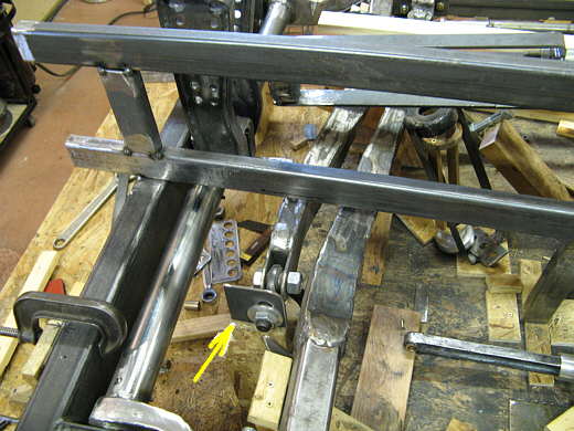
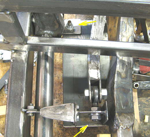
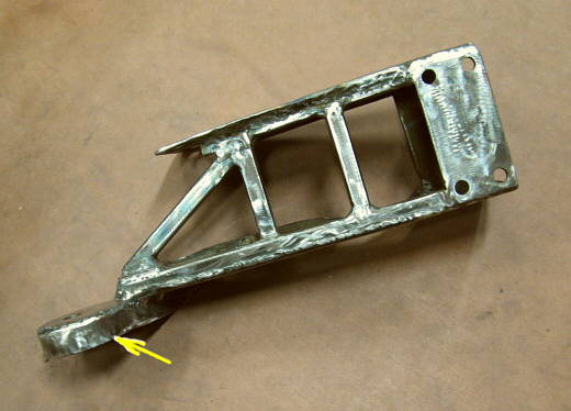
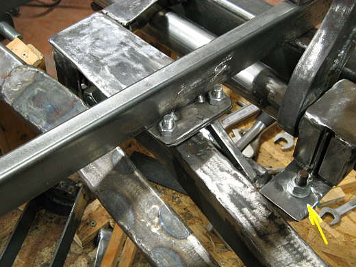
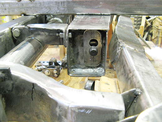
The problem to solve here is how to locate the axle end (arrow) so that it is supported up and down, side to side and front to back. All of this can't exceed 4-5 inches in height outside the main body frame rails and I have to make sure I can get the lever arm assemble out. This all proved to be somewhat of a pain.
................... .
.
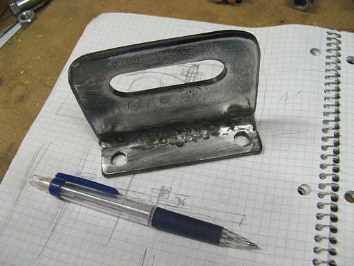
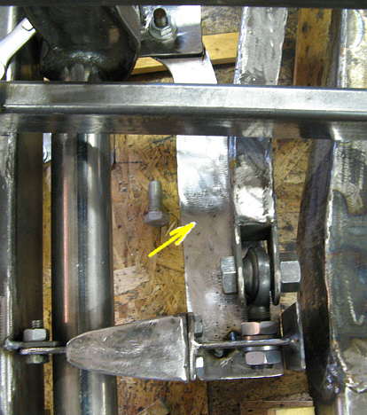
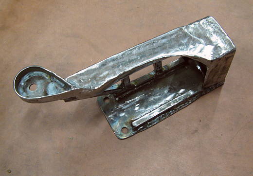
This bracket will be welded on to the side of the one above where the arrow is pointing. The holes will be to bolt other brackets to that will limit the axle's movement front and rear.
................... .
.
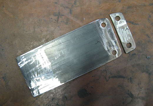
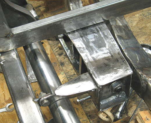
The last bracket welded to the first one. The slot is for the heim joint to move up in down in to set the final camber of the right wheel.
...................
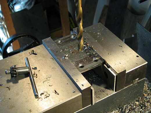
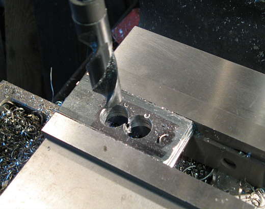
There are two pieces here that are being drilled to match the holes in the bracket in the last picture.
...................
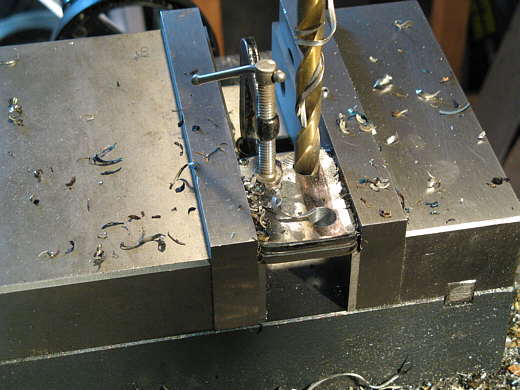
One of the pieces from the last picture bolted on with an arm welded to it that clears the lever arm.
...................
Another piece was added to the arm to brace it and a tab was tacked to the crossmember that the arm will attach to. The tab will get a reinforcing piece later.
................... .
.
The finished arm for the top. Later I'll make a similar one that will go under the lever arm. The two of these will keep the axle mount from moving forwards or rearwards.
................... .
.
The axle mount got a second vertical piece welded to the other side. When the mount is done it will be boxed in all the way around.
................... .
.
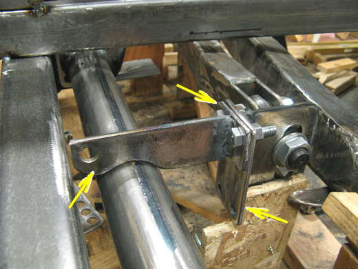
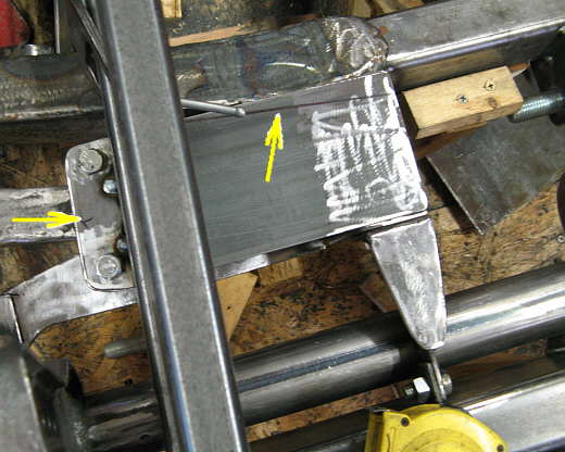
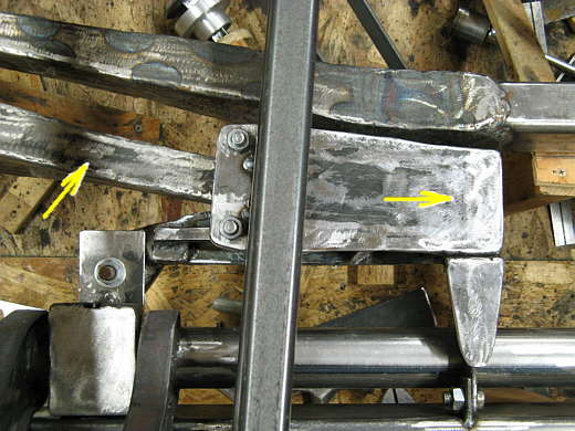
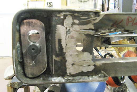
To prevent the mount from moving side to side a top piece and a bottom piece was added to it. I started by drilling a hole in the piece that the lever arm pillow blocks are sitting on (top arrow). A plate was bolted to the hole. The plate came over to the axle mount (bottom arrow). With the plate in place I marked the final shape that I wanted it so that it would clear things.
................................ .
.
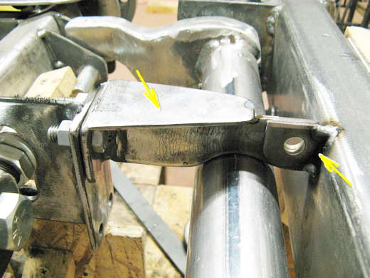
It was cut to the shape above (arrow) and welded to the bottom of the axle mount assembly at the bottom of the picture.
................... .
.
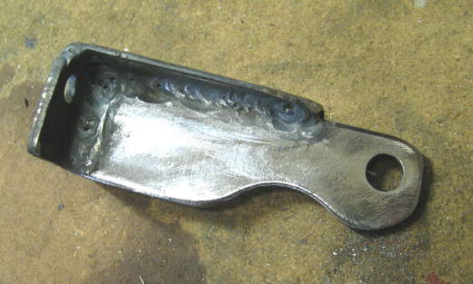
A top plate and a bracket to attach it to the frame were made next.
................... .
.
The bracket was tacked to the frame (left arrow) and the plate was bolted to it and after it also was marked and cut was welded to the axle bracket. The arrow points to a cut line at this point.
................... .
.
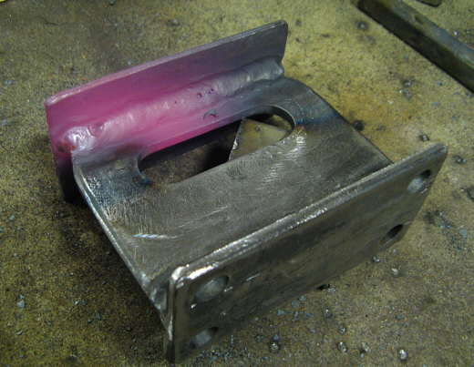
The bottom and top plates needed to be reinforced to keep them from bending. I welded a piece of strap around the bottom of the left end mounting hole (arrow) and added 1/2 inch square tubing to the rest of the assembly to make it into a girder type assembly.
................... .
.
In this view it is upside down. A lot of work went into this to make sure it cleared the axle as the axle goes through suspension travel.
................... .
.
The final assembly in place. Note I still need to make another arm for the bottom of the assembly that will go under the lever arm. The two arms are bolted on so that the lever arm can be removed without removing the whole axle assembly.
...................
The left arrow points to the axle that goes to the left in the picture over to the right front wheel of the car. The right arrow points to the pivot point of the axle in the assembly that has been constructed on this page.
...................
Another view. The plate that the assembly attaches to (arrow) will be reinforced when I build the pieces that will support the pillow blocks that are sitting on the plate. The top mounting point in the picture that is just tacked at this point will also get reinforcement.
...................
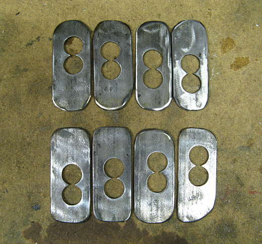
As I mentioned above the heim joints on the ends of the axles can move up and down in slots to set the camber. Likewise there are heim joints on the ends of the front radius arms that can slide up and down in slots to adjust the castor to some degree (see page 62) . I wanted to make a way to positively lock the heim joint ends in different position in the slots. I took 4 plates and drilled two holes. One hole is in the middle of the travel and the other is at the top of the travel. Next I took 4 more plates and drilled two more holes in them. One 3/4 inch hole is 1/4 inch above center and the other is 1/2 inch below center.
................... .
.
Depending on how the plates are positioned (you can flip them end for end) this gives 7 positions 1/4 inch apart. 1/4 inch is way less than a degree of camber, so this will work fine.
................... .
.
Here one of the plates is locking the end of the heim joint on the radius arm in the middle position of its travel.
................... .
.
This plate is locking the axle heim in the middle position. Of course in both of these pictures a nut will go on the end of the threads of the heim and pull it tight against the slotted plate. There is a lock nut on the other side of the slotted plate.
................... .
.
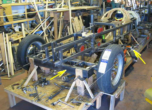
A view of the from to the car showing things at this point. Notice how the front axles and suspension pieces and locators all fit right behind the front cross member (left arrow) and are not higher or lower than it is. The string (right arrow) is being used to string the car and make sure the wheel is just where I want it so I can start building the assembly on the right side of the car that will locate the left axle and left wheel.
................... .
.
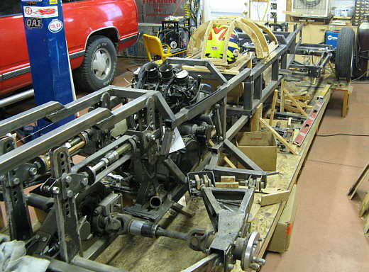
A picture from the rear. Notice that in front of and behind the cage the car is always tapering. I don't want flat sides on the car.
........................ .
.
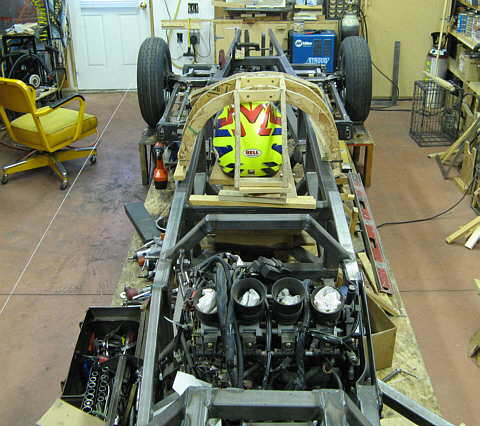
And a view from above.
..............................................................Next Page