...Return To Mine & Other Bonneville Car Construction Pages
.Previous Page...............B'ville Car Index Page.........................Next Page
...................................Radius Rod End Mounts
................. .
.
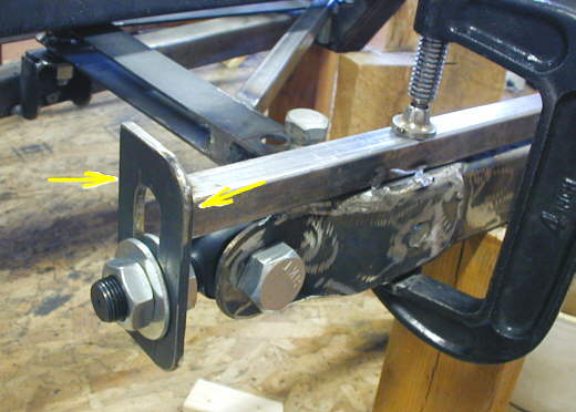
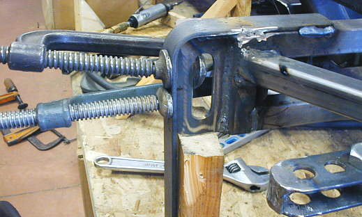
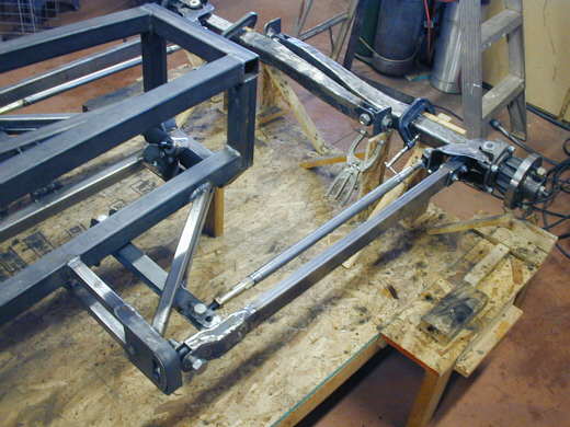
Next up is making a mount that locates the end of the front radius rods (similar to split wishbones on an early Ford). I started with the slotted piece (left arrow) and mounted it to the end of the radius rod at the correct height off the build table. Remember everything that is outside of the body on the sides of the car has to fit within the same 5 inch vertical height 10 inches off the build table. Since the heim joint let the slotted piece fall down I tacked a piece of square tubing to the slotted piece and clamped it to the radius rod in the correct position. The temporary square tubing was later removed.
................. .
.
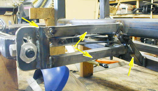
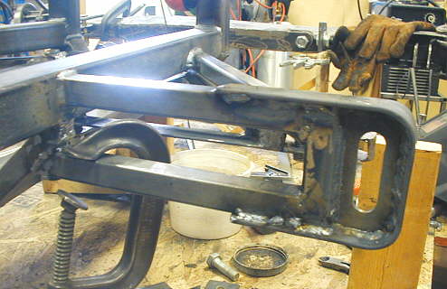
A piece of 1 inch square was welded to the slotted piece (left arrow). A diagonal piece was welded to the cage (right arrow). Then the two pieces of horizontal square tubing (middle arrows) were welded in. These pieces locate the end of the radius rods at a position away from the body.
................. ....................
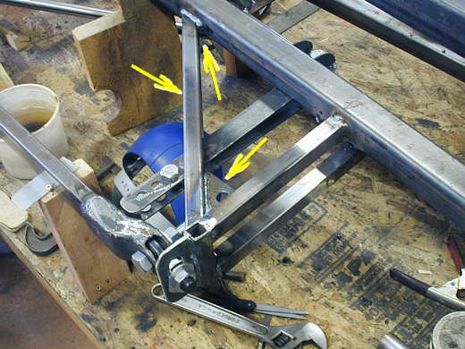
A diagonal (left arrow) was welded between the cage and the outrigger. This will take the fore/aft loads on the mount (the major loading on the mount). To reinforce this union one bracket (bottom right arrow) was welded between the diagonal and the outrigger. Later another bracket will be welded in (top right arrow) when the car is turned over to weld all the bottom welds.
...................................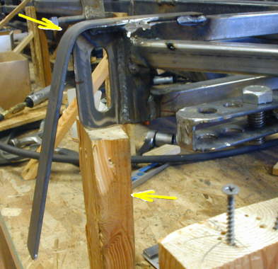
Finally I needed to beef up the slotted piece so that it would not bend with the fore/aft loads pressing on it from the radius rod. I took a 3/16 thick by 1 1/4 inch wide piece of strap and welded it to the top of the out-rigger and then proceeded to bend it around the slotted piece. The 2 X 4 (arrow) supported the out-rigger while I bent the strap and beat on it with a hand sledge hammer.
..................
As I bent the strap around the slotted piece I used clamps to hold it tight and proceeded to weld the two pieces together.
......................
The finished out-rigger except I'll add some strap to tie the out-rigger to the cage.
...................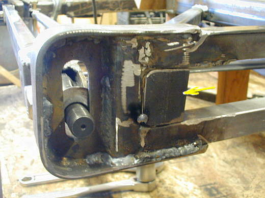
I needed to make some system to prevent the nuts on the end of the heim joints from coming off to meet the rules "All front end and suspension fasteners shall be aircraft type 'self locking nuts or have wires or keys appropriated placed to prevent them from coming apart". I started by welding in these tabs (arrow). Here it is just held by a tack weld, but was then welded to the three pieces of square tubing.
...................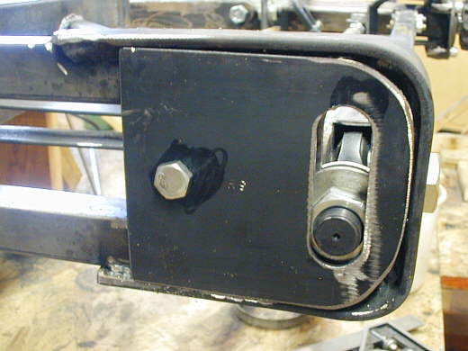
I then made some slotted plates and drilled a hole through them and the tab in the previous picture for the bolt you see in the picture. These plates are bolted to the end of the out-rigger and clamp against the nut on the end of the heim joint and trap the nut between the two slotted pieces.
...................
Now the front is located fore-aft and the steering is in place along with the front axles.
...................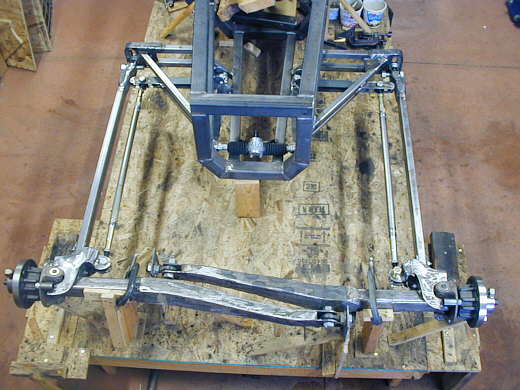
I'll now move on to the suspension components for the front and the support for the ends of the in-board ends of the axles.
...................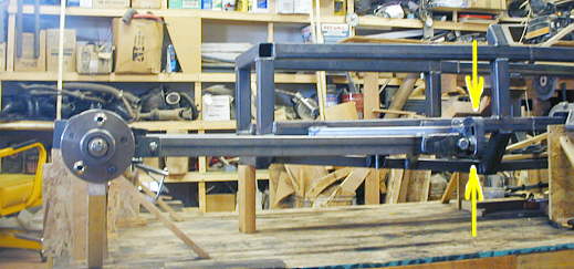
This view shows how all of the components put into place to this point fit inside the 5 inch plane between the two arrows. This is important to keep the frontal area of the car as small as possible.
..................................................................Next Page