...Return To Mine & Other Bonneville Car Construction Pages
.Previous Page...............B'ville Car Index Page.........................Next Page
....................Front Suspension Lever Arms -- Part I
.................. .
.
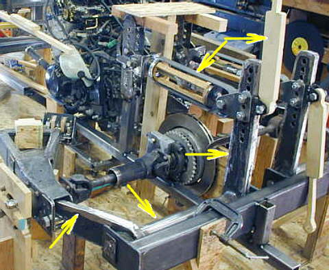
This is a picture of the lever arm I made for the rear suspension (3 bottom arrows). It rides on a bolt (left bottom arrow) that is on the outer part of the axle. As the axle goes up it moves the arm up which is welded to the tube (center bottom arrow). On the other end of the tube is a vertical lever arm (right bottom arrow) that pulls on the spring (top left arrow) and pushes on the shock (top right arrow). The shock should be in a horizontal position. If you didn't see how I built all of this you can go back to (HERE).
The reason for the lever arm assembly is to move the suspension of the rear axle to the middle of the car for aero reasons. This lever arm rotated on a 1 inch diameter piece of cold rolled steel that ran the length of the lever arm and pivoted on aluminum bearings that fit into the ends of the tube.
For the front I wanted something similar, but I wanted to put short pieces of 1 inch cold rolled steel inside the two ends of the lever arm assembly and have them pivot on pillow blocks at the ends of the lever arms. On this page I'll make the pillow blocks and cold rolled steel inserts for the ends of the lever arm tubes.
............. .
.
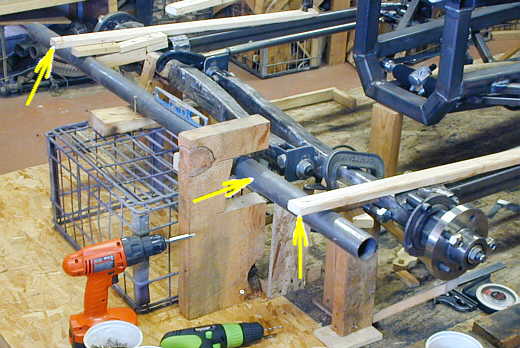
To start I put the DOM round tube (center arrow) into place that will be cut into two tubes for the main section of the front lever arm assembly. Here again we see my piece of wood with the cut-out. I have to make sure all of this fits into the 5 inch cut-to to match everything else I've built that will stick out past the body. The two outer arrows show me where the inside of the front tire will be with the tire turned to the maximum. So everything has to also fit between the two outer arrows. Right now you can see the tube is way too long and it will be cut in half so that the suspension will be independent for each side.
............. .
.
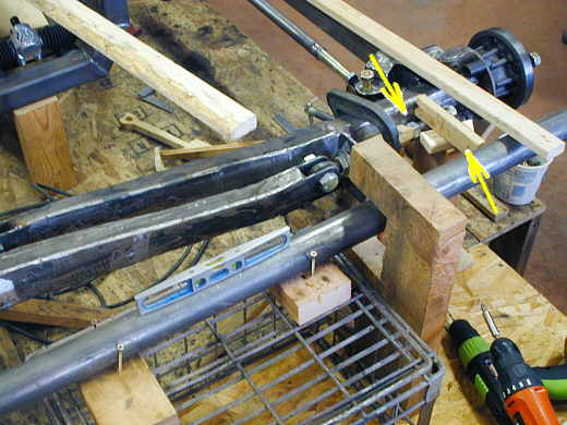
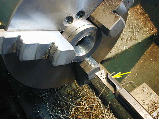
The left arrow here points to the bolt that the lever arm will ride on. I'll make a bracket that will attach to the end of the axle and hold the bolt in this position. The right arrow represents a 7 inch lever that will be welded to this end of the lever tube. It is 6 inches from the center of the tube to the center of the bolt on the axle.
............. ....................
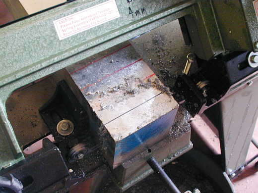
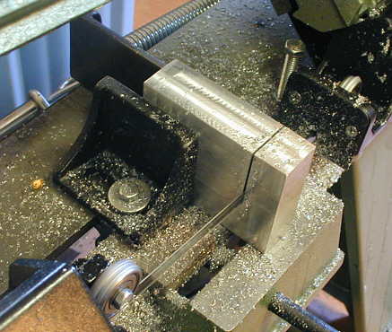
Now the point of this build page is to build the parts that will allow the lever arm to pivot as the axle moves up and down. I had a piece of aluminum that was 4 inches square and about 24 inches long that I found in a salvage yard. I'll use it to make the pillow blocks for the ends of the lever arm assembly. I'll make the blocks 3 X 3 X 1 1/16 inches with a 1 inch diameter hole in the center of them. I started by cutting the raw stock about 1 1/8 inch thick.
.......................
After I had them rough cut for thickness I made two more cuts to get them to almost 3 X 3.
.......................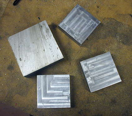
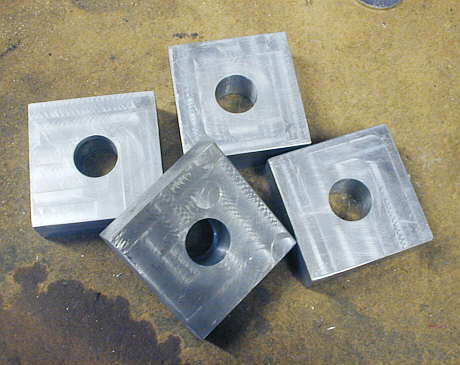
Here you can see 3 of the blocks almost done. You can also see the milling marks left from using the mill to get them to exactly 3 X 3 X 1.063 inches and square on all the sides.
..............................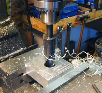
Each block was then drilled for a 7/8 inch dia. hole in the center of them.
...........................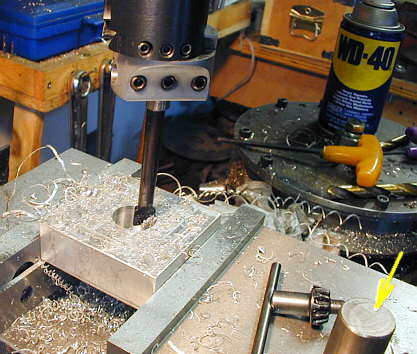
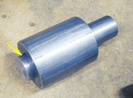
I then bored them from 7/8 inch out to 1 inch with a boring bar. The arrow points to a piece of 1 inch cold rolled steel that I used to make sure I had the holes the way I wanted with a better clearance fit than I would have gotten by just drilling them out with a 1 inch bit.
......................
Here are the four bearing blocks that will be used on each end of the two lever arm assemblies.
.................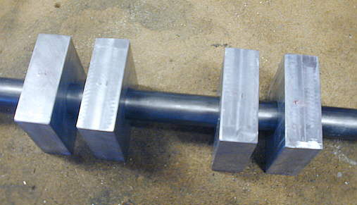
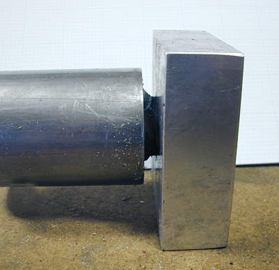
This shows how the one inch cold rolled pivots inside the bearing blocks. Next I'll make the assemblies made up of 1 inch cold rolled steel and some 3/16 strap that will fit into the ends of the lever tube and pivot on these bearing blocks.
...................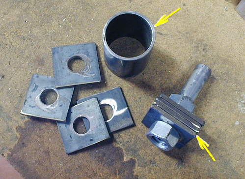
I cut a piece of tubing (top arrow) that I'll use as a jig to make the pivot assemblies all the same. I cut off 8 pieces of 3/16 by 2 inch flat strap and drilled a 3/4 inch hole in all of them in one operation holding them all at the same time in the vise on the mill. I then took 4 of these at a time and mounted them on a cut-off 3/4 inch bolt.
........................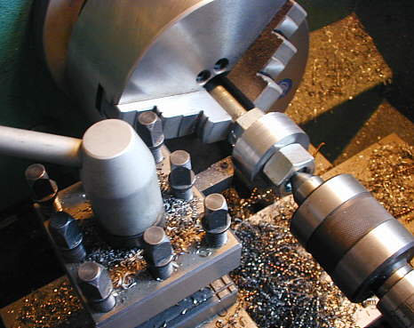
The bolt with the 4 pieces on it were put into the 3 jaw chuck on the lathe and I turned the pieces down so that they would just fit into the 2 inch dia. DOM tubing I'm using for the center piece of the lever arm assembly.
..................
Following the above step using a boring bar (arrow) the centers were bored out to 1 inch so they could be mounted on the 1 inch cold rolled steel.
...........................
Using my jig (the piece of 2 inch dia. DOM) the previous made pieces were placed inside of it and a piece of 1 inch cold rolled steel 4 3/16 inches was placed inside of those and was left sticking out 1/4 inch on one end. I then tack welded the cold roll to the washer like pieces............
.................................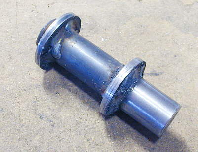
...............pulled it out of the jig and finished welding it into one piece.
......................................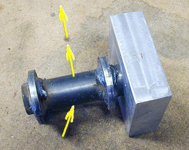
This piece (bottom arrow) will be welded into the end of the lever arm tube and will pivot on the bearing block. The two top arrows represent the direction the lever arm that will ride on the front axle will be in respect to the main tube.
..................................
This is how this will look in final application. There will still be some threaded mounting holes put into the bearing blocks. Ok I have to make the other 3 and go on to the next step
..................................................................Next Page