...Return To Mine & Other Bonneville Car Construction Pages
.Previous Page...............B'ville Car Index Page.........................Next Page
....................--- Rear Suspension Part I the Tube---
.............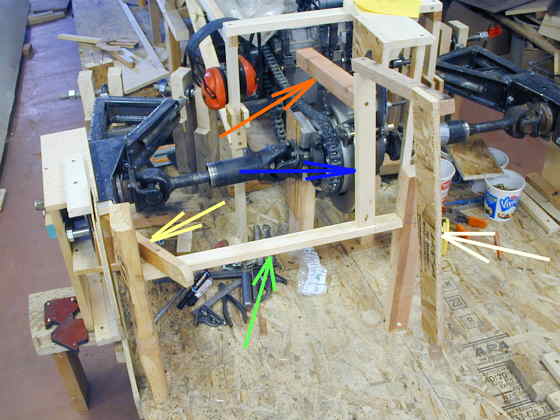
Now that the rear control arms are done I'm moving on to the suspension that I hope will work when completed. I want the shocks and springs to be inboard yet be acted upon by the outboard hubs/wheel/tire. To do this I will use a tube (Green Arrow) that has a lever arm (Yellow Arrow) on one end going to the 3/4 inch bolt on the back of the hub and another lever arm (Blue Arrow) on the other end that will act upon a shock (Cream Arrow) and spring (Red Arrow). This will be duplicated for both sides of the rear. The inboard lever arm will pull on the spring and push on the shock.
..................... .
.
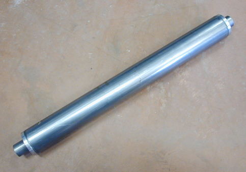
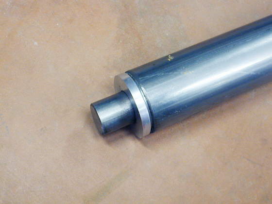
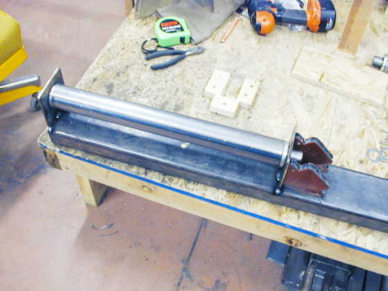
Here is one of the final tubes that the lever arms will be attached to. It is 2 inch DOM tubing. In each end is an aluminum bushing (see below) and all the way through the tube and the two bushings is a piece of 1 inch cold rolled steel. The inner round (cold rolled steel) bar will be supported on it's ends and the tube/bushings will rotate on it.
.............. .
.
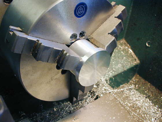
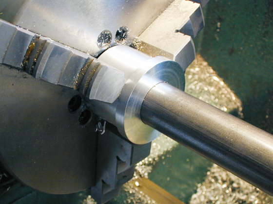
I bought some pieces of 2 inch round aluminum on eBay and used them to make the bushings that go into the ends of the main tube. I machined them a couple different ways, but basically I just cleaned up the overall diameter and kept it as close to 2 inches as possible. Then I machined about 1 1/4 inches down to the correct diameter to fit into the tube. Next I cut them off with the bandsaw so that the large diameter (2 inch dia. part) was a little over 1/4 inch long.
.............. .
.
I took the shortened piece and cleaned up the bandsaw cut so that the end was flat and there was a 1/4 inch length before it stepped down.
............... .
.
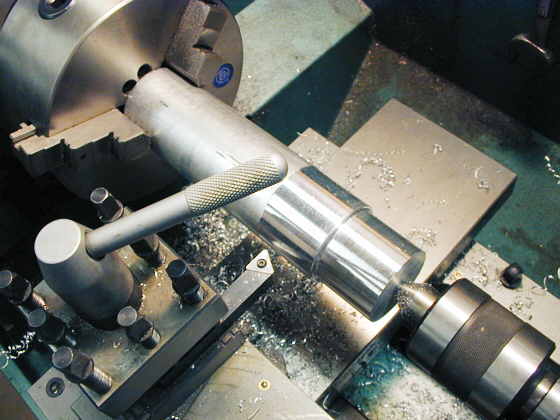
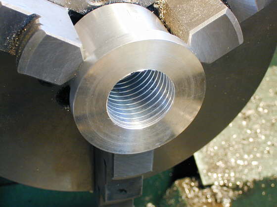
I then bored the center out to a 1 inch diameter for the cold rolled bar. Here I'm checking the fit of the bar in the bushing.
............... .
.
Last I took my boring bar and set it to make about a .025 cut into the bore walls. I set the lathe to the slowest speed and then hand feed the boring bar into the bore at a rate that I though "looked good". The resulting spiral groove in the bore is to help hold grease later when the whole thing is assembled. These bushings will only turn through a few degrees of movement.
............... .
.
Here is a close-up of the one finished bushing installed in the round tube.
............... .
.
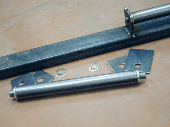
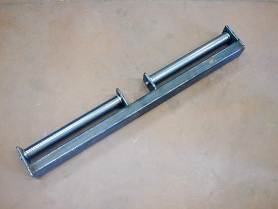
I cut a piece of .120 X 2 X 4 tubing the length I wanted for a rear crossmember. This piece will later be attached to the rest of the frame and it will support the tubes/lever arms. I cut and drilled brackets to attach to the crossmember. I wanted some width to the brackets for the cold rolled bar to sit on. I don't trust my welder to do a good job on 3/8" stock, so I cut two 3/16" pieces of strap for both the inner and outer supports. I also decided on 2 thrust like washers for both ends of the tube. You can see all of that in the picture above.
............... .
.
Using some 90 deg. magnets I welded one set of brackets to each end of the tube assembly. You can see the space at each end of the tube that the thrust washers create. This helps to keep the bushings in the tube ends off of the brackets.
............... .
.
I then welded the other two brackets on to the ends and repeated all of this for the other end of the crossmember. On the ends of the crossmember there is one short bracket that just goes to the crossmember and a longer one that goes across the end of the crossmember. The inner support for both tubes is 2 identical brackets welded together and to the crossmember. You can see all of the brackets for one side in the picture before this one.
............... .
.
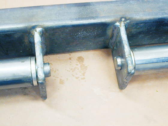
Here is a close-up where you can see I've welded 2 pieces of 3/16 inch strap together to form a thicker piece. I have some more I'll do to the cold rolled pieces later to secure them in the brackets and to keep them from rotating. The bushings seem to to a very good job at this point.
............... .
.
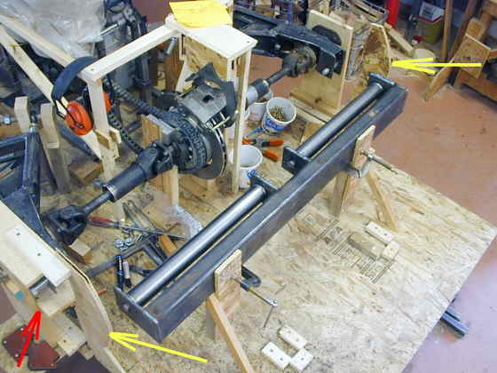
Here the crossmember is in place. Next is the inner and outer lever arms that will go on the two tubes. The space between the two tubes is 7 inches. That will keep the shocks in the rear at least 7 inches apart and give me room to run the parachute tube down the middle between them. The Yellow Arrows are pointing to pieces of wood that represent the inboard sides of the tires/wheels. The Red Arrow points to where I've placed pieces of wood to represent the upper and lower limits of suspension travel.
When I say the lever arm will pull on the springs that is actually right, but not right. The lever arm will be pulling on the end of the spring that is furthermost away from the lever arm. The end closest to the lever arm will be held from the opposite end of the spring, so the spring will be in compression. The lever arm itself will not be touching the spring. Not sure if I'm explaining this clearly??? Also the spring end closest to the lever arm will be pulled on from the other end in such a way I can adjust the ride height. Doing this will allow me to tuck the springs horizontally up close to the body sides above the rearend parallel to the frame and keep the center of this area open for maybe the intercooler. This will keep some more of the weight forward. The shocks can be tucked in between the body and chute tube/tubes where the tail is tapering in.
The rear crossmember weighs about 17 lbs. and the total of the crossmember
with the two tube assemblies came in about 38 lbs..
..................................................................Next
Page