...Return To Mine & Other Bonneville Car Construction Pages
.Previous Page...............B'ville Car Index Page.........................Next Page
............................................. Finish 2nd Front Axle
.............................Start of Radius Rods & Steering
.................. .
.
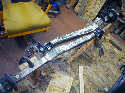
A view of the finish 2nd axle along with the first.
.................. .
.
As usual I didn't like having to make the second one, but it does always go faster. I got the curved part done in a couple hours.
................................... ....................
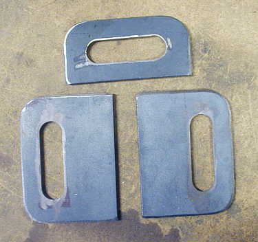
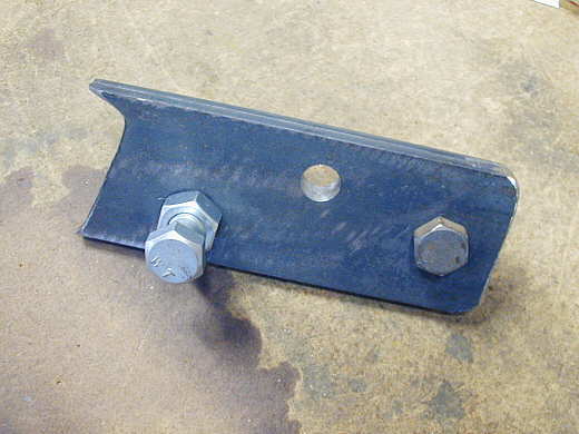
I decided that I needed to make new plates that locate the ends of the axles as the other ones weren't wide enough for the bolts that go through the heim joint at the end of the axle (to take into account the head of the bolt and the nut side of the bolt).
.................. .
.
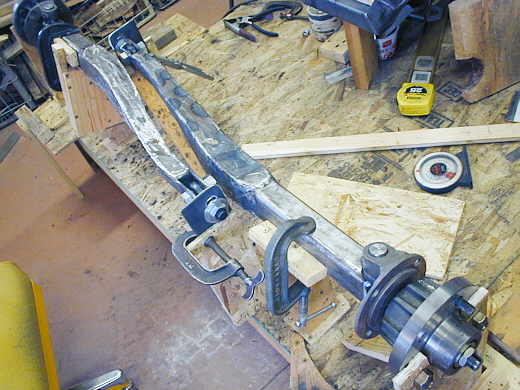
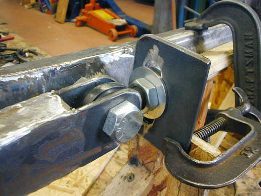
Here the new end is in place. They will be welded to crossmembers and reinforced with webbing.
.............................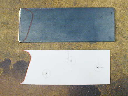
Next I started on the brackets that will mount to the axles near the spindle. The radius bars will attach to these brackets and will locate the front axles. I made a paper pattern with a protractor (to get the 18 deg. angle of the front axle for the castor) and a piece of cutoff 2 X 2 square tubing (the cross-section of the axles). I also located the attachment holes. I transferred all of that to two pieces of 3/16 X 2 inch strap.
.................................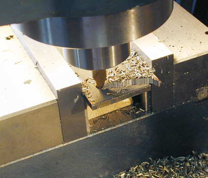
I put the strap in the mill and used a 1/4 inch end mill to cut close to my line. My X-Y feed is all hand feed, so I just try and get close and rough it in to save a bunch of grinding. This step only took a couple minutes. Like I've said many times, get a mill and lathe if you want to do a project like this.
....................
Here is the piece laid on top of the paper pattern. You can see I got pretty close.
....................
After I had the second one close I clamped them together and worked on them with the grinder for a few minutes to get closer using the piece of 2 X 2 square tubing.
....................
Then I kept the two pieces together and put them in the vise on the mill and drilled the first hole through both pieces. After the first hole was drilled I inserted a bolt to make sure they didn't move in relation to each other and drilled the remaining two holes. Next I put a second bolt in to hold them together and went back to the hand grinder and finished them up.
............................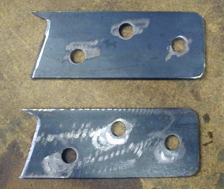
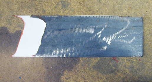
Here are the two 99% identical pieces after probably 45 minutes work or so.
...................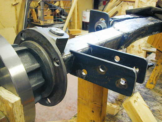
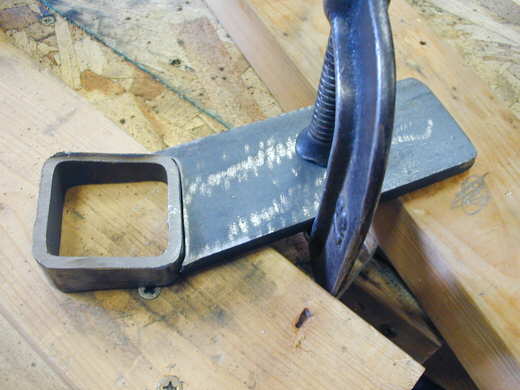
This is close to the position they will be in. There will be some more strap that will tie the tops and bottoms of them to the axle. Before I start welding them into place I need to finish the steering arms and the rest of the steering parts. I did these to this point to know where I'm at when designing and making the steering arms so they will clear these brackets.
........................
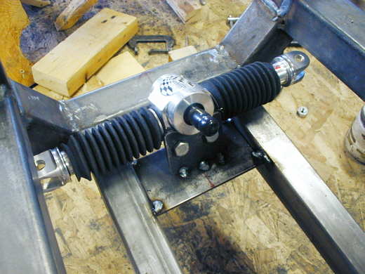
So it was on to the steering. I bought this B'ville ratio rack ( see parts I've used page ) that can can be mounted at any angle and the ends indexed to whatever position you need. I took a piece of 3/16 strap and made the bracket that you see attached to the rack.
...................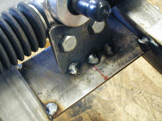
I welded a flat plate between the bottom rails of the cage at the needed height and then welded the rack/bracket to the plate at the desired angle.
...................
A picture showing how the rack is located on the floor at the front of the cage area. The pedals will be right above it and in front of it with the steering column going back between my legs.. I went through about three different locations for the rack and different scenarios for the steering before deciding on this location and method. I want to get it all mocked in and try it before I go any further with the frontend in case my ideas don't work out.
...................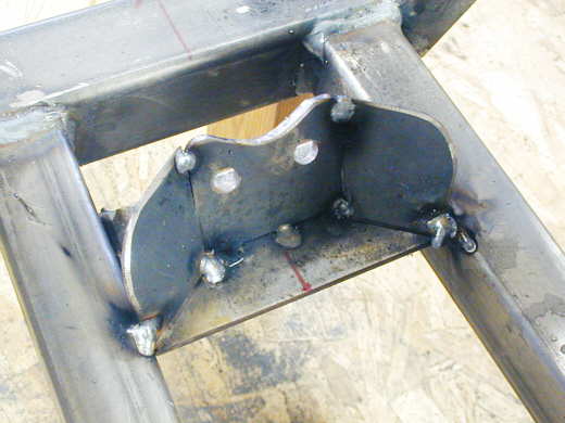
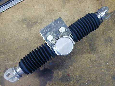
I wanted to further reinforce the bracket that holds the rack, so I made these pieces that attach to it at about 45 degrees.
...................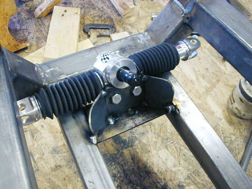
The finished mounting system for the rack. I'm just tacking everything at this point until I'm sure it will work. If you tried to figure out how the front suspension is going to work from the drawings a few pages back I hate to tell you, but it was wasted time. I'm looking at a simpler solution at this time.
..................................................................Next Page