............................... Previous Page.................................................. Next Page If There Is One
..................
..................--- Spare Tire Holder - Tongue Wheel/Axle ---
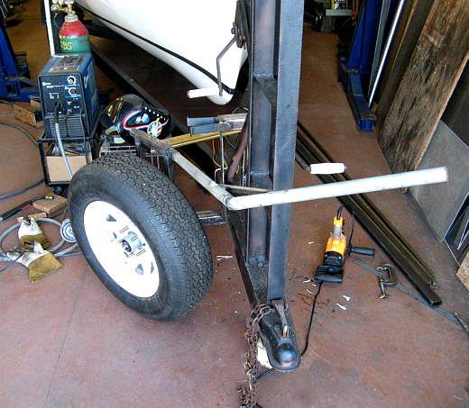
The trailer we got with our Mac didn't have a spare tire or a holder for one. I decided to add one to the trailer. Along with adding a mount I wanted to try something in conjunction with it. The ramp at our local lake is not very steep. It was actually the road that led north out of town until the lake was put in and then the road was moved to run across the top of the dam. Since the ramp isn't very steep you have to back a long ways out into the water to get the boat off of the trailer. I wanted to make a push/pull bar to go between the tow vehicle and the trailer to add some distance between them. For this to work I needed a wheel on the tongue of the trailer to support the tongue.
I decided to make two receivers to hold the spare tire with one lower than the other. I would use the lower one when I wanted the spare to be the tongue wheel. I also wanted to be able to steer this wheel as that would be necessary when pushing the trailer with the bar between it and the tow vehicle. We are using the 4 wheel drive Jeep at the moment as the tow vehicle, but at other times we might be using a 2 wheel drive vehicle. I though that if this works that this setup might help at other ramps where maybe the ramp is slick and this would help to get the tow vehicle up on drier ground.
Well what follows is how I did all of this and later I'll get back and let you know if it worked or not, Sum.
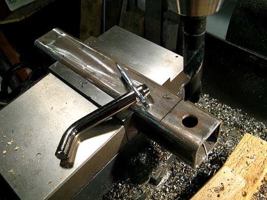
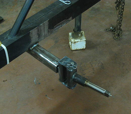
..........I started by making the bottom receiver. It was drilled on the end for the 5/8 inch pin that will be used.
..................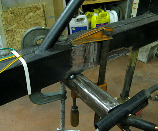
It was tacked (I tack everything until I see if it works) in place on the bottom of the tongue. It was offset to the starboard side enough so that the wheel will be steerable.
..................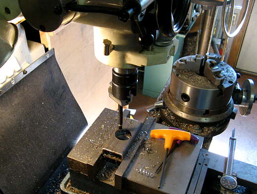
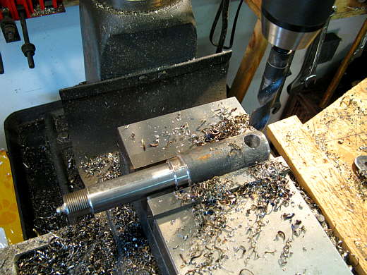
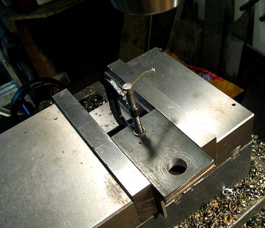
For the wheel to turn I needed to make a spindle and axle for the wheel/tire to mount to. The axle will go in the receiver I made in the first two pictures. I bought a stub axle, the kind you can get to make your own axles. To make the spindle this piece of 1 X 2 rectangular tubing was drilled then bored to 1 1/2 inches (above).
..................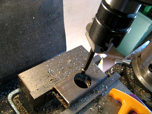
Here the boring part is being finished. The hole also could of been made with a hole saw.
..................
Next a 11/16 inch hole was drilled in the stub end of the short axle piece.
..................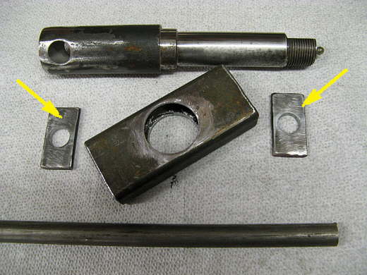
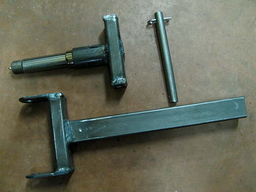
These are the pieces to make the spindle. The arrow points to the top and bottom pieces that are drilled to 5/8 inch and the bar at the bottom will be shortened and will become the king pin. The hole in the axle was made larger to easy assembly.
..................
The arrows point to the king pin (it will be shortened) then the pieces were put together for a trial fit before .......................
..................
....... it was tacked together.
..................
Now to make the axle that the spindle will be attached to. Here two plates are being drilled to 5/8 inch for the king pin to go through.
..................
The two pieces from the previous picture (top two arrows) were then held to the spindle and another piece of 1 X 2 rectangular tubing was cut and put between them. These pieces.......
..................
.......... were then welded to a piece of square tubing resulting in the axle. The 5/8 inch round rod was cut to length and drilled on both ends for pins (only the top one is shown). Now we have..........
..................
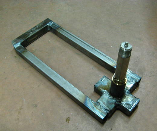
..... the axle, spindle and king pin. The end of the axle had also receiver a hole for a receiver pin to go into.
..................
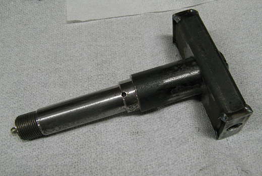
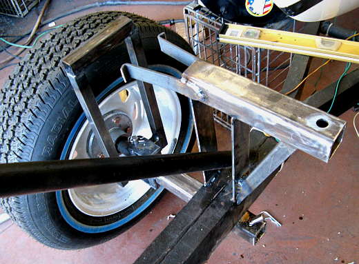
Here the axle assembly has been slid into the bottom receiver for a trial run.
..................
I wanted the wheel to be steerable, so these pieces were added to the spindle.
..................
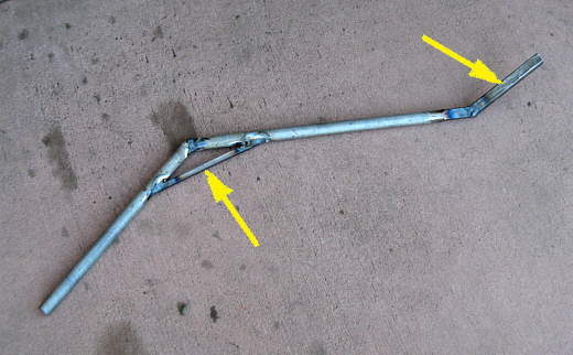
A tiller was made from some square tubing and round tubing and it slides into the top of the steerable spindle. In this picture the wheel tire has been turned in one direction with the tiller handle .......... and ..................
..................
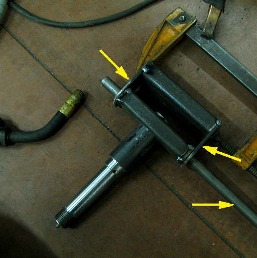
...........in this picture the other direction. The two left arrows point to the steering handle and the top right arrow points the square tubing receiver that the handle slides into.
..................
Here you can see how the handle has a bend in it to go around the ladder on the front of the trailer. It can be steered from the ground or while standing up on the ladder if you are in the water.
..................
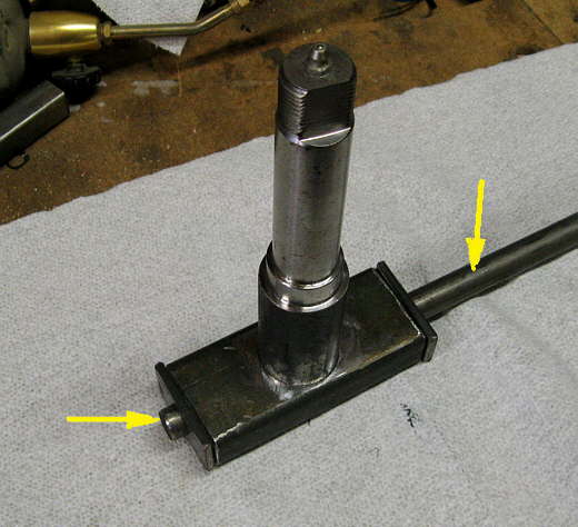
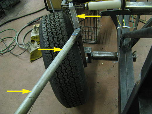
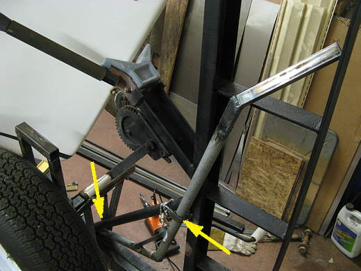
The left arrow point to a brace that was added even though the handle seemed strong enough without it. The right arrow points to the square tubing that slides into the other square tubing at the top of the spindle assembly.
..................
The handle stores with the bottom jammed in down by the front diagonal piece that reinforces the ladder on the front of the trailer. Part way up the handle fits into a "U" shaped piece that was welded to the ladder. It fits snug, but....................
..................
........a chain was added with a snap hook on the end of it to just make sure it doesn't come loose from the trailer.
..................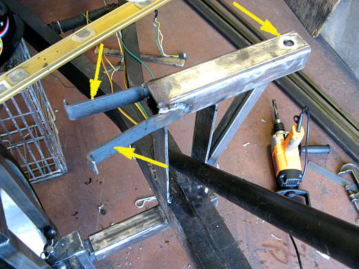
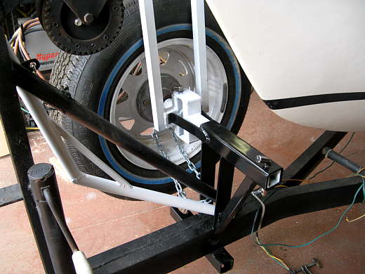
Next a top receiver was built above the lower one. This is the one used to hold the wheel/tire when traveling and/or while in storage. It has a hole on the right side (right arrow) for the receiver pin to go into. The ears on the left side (two left arrows) keep the tire from turning one way or another on the spindle.
..................
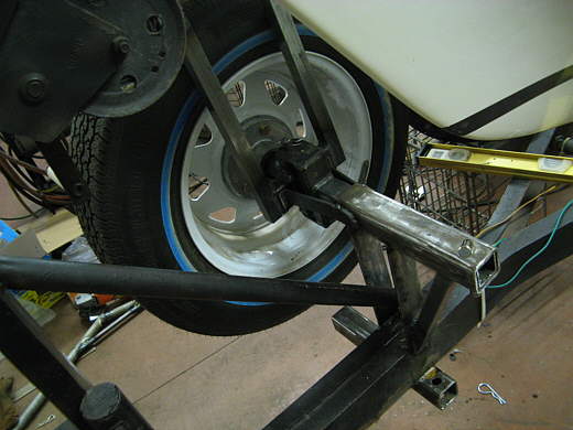
A view from the other side with the tire/wheel still in the bottom receiver.
..................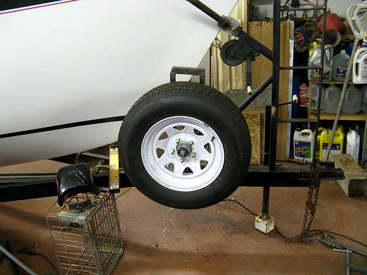
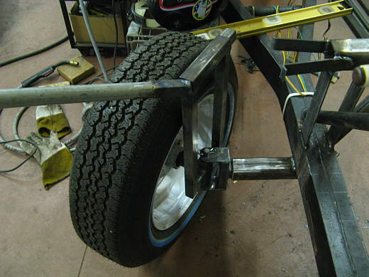
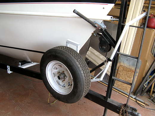
Here the tire/wheel or mounted in the "spare tire" position..... and .....
..................
.......... a view from the other side.
..................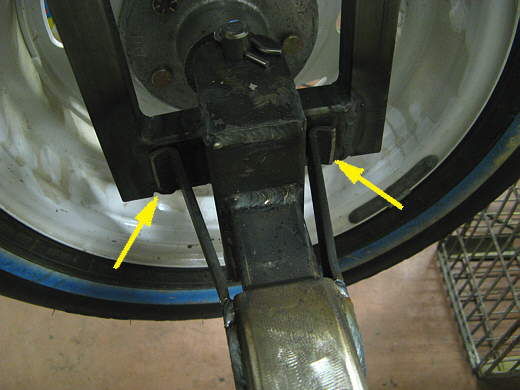
A close-up showing how the ears jamb against the spindle assembly and keep it from turning. The tire can still spin and there will be a chain through it with a lock. That will keep it from spinning and hopefully also from finding a new home. I'll report back after I get to try this out and will let you know if it worked as planned.
..................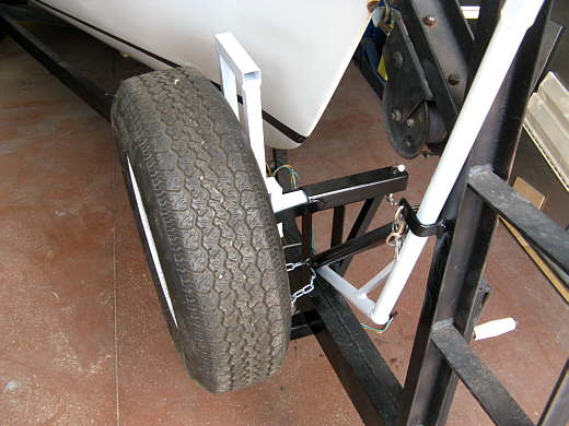
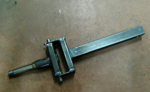
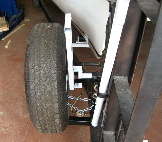
Here are four pictures after everything was painted......
..................
.................
..................
.................
..................
.................