..................
................,,,,..........--- New Centerboard Support/Roller ---
..............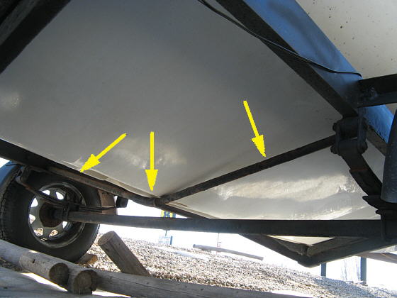
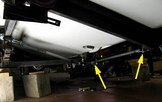
The MacGregor trailer has this round tubing going from side to side (arrows) that is there to catch the swing keel (centerboard) so that the rope/cable used to pull it up and down doesn't have to support it going down the road.
..............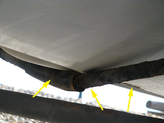
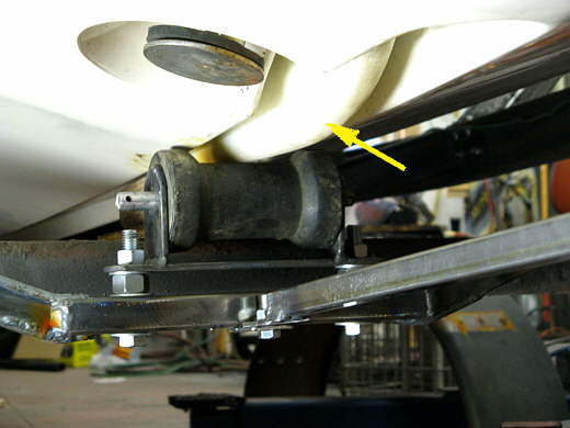
Besides the centerboard resting on the bar which is ok the bottom of the boat itself was hitting the tube instead of being above it. The tube is severely rusted and needs to be replaced. Also you can see where the axle at times has hit the bottom of the boat (forward arrow). I think this is a combination of sagging springs and compressed old wood in the bunks. A little more clearance was created between the boat by making......
..............
................ rear spring shackles that were about 1 1/4 inches longer. That added about 5/8 of an inch clearance. I didn't want to go longer with the shackles as long ones bend easier. Longer shackles are normally available, but at the moment there was none to be found in town, so I made these from .250 X 1 1/2 inch strap. Soon I also hope to replace the wood bunks with some that are also a little thicker and later the trailer will get a second axle with disc brakes.
Now on to replacing the rusted out centerboard support tube.
..............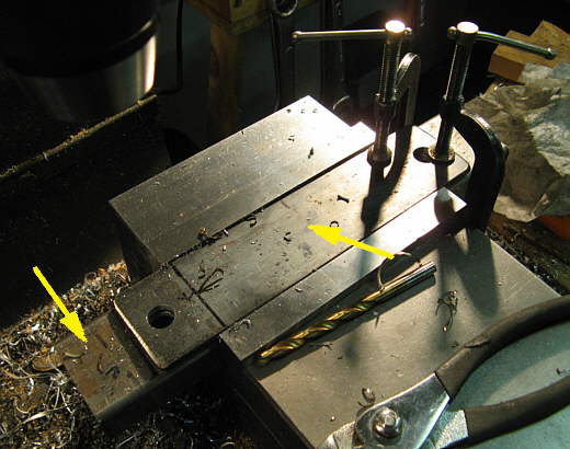
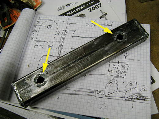
A piece of .120 X 1 X 2 inch rectangular tubing (left arrow) was positioned in the vise with a piece of 3/16 X 2 inch strap above it. Then 1/2 inch holes were drilled through both. Actually I have a 17/32 bit I use to make the hole slightly larger than 1/2 inch for bolt clearance after painting.
..............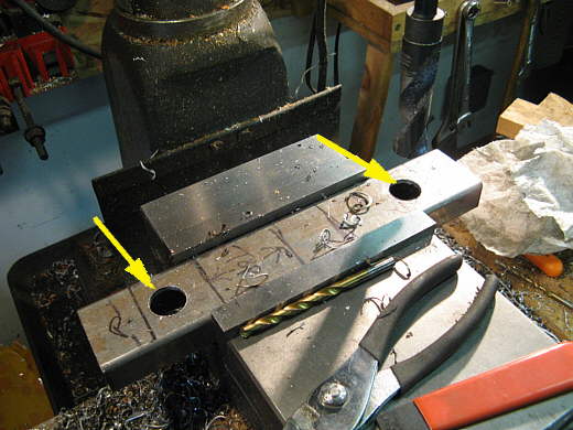
The strap was removed and then the holes in the rectangular tubing were drilled out to 7/8ths of an inch.
..............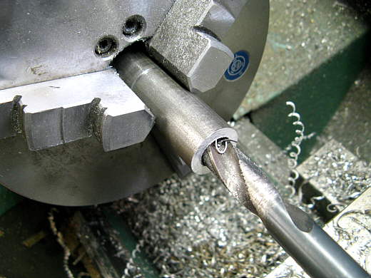
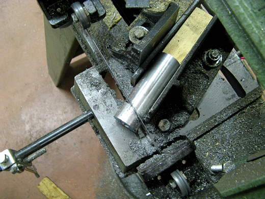
The a piece of 7/8 this round stock was also drilled out to 17/32 of an inch.
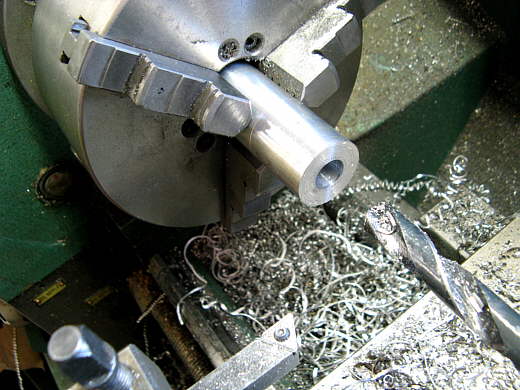
..............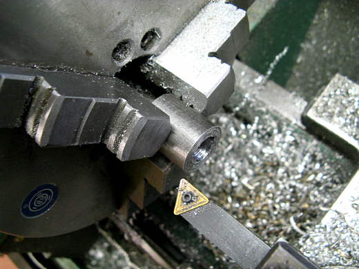
The round stock was cut into two lengths a little longer than 2 inches with the band saw and then faced down to 2 inches back in the lathe.
..............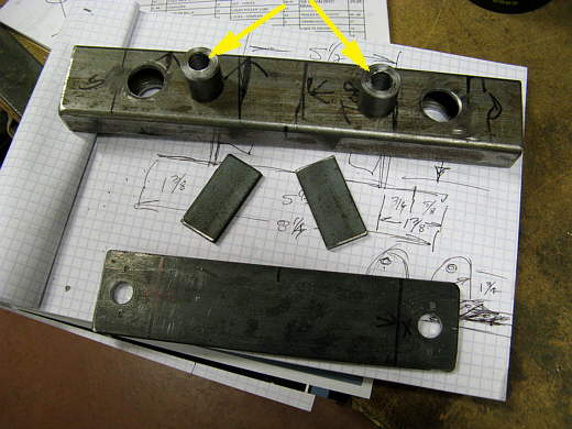
The round stock bushings just made will go into the 7/8ths holes in the rectangular tubing. This will keep the tubing from being crushed when the bolts go through it and after I weld plates on the end of the tubing (middle two piece) no water can get in the tubing to rust if from the inside.
..............
Here the end caps have been welded on and the bushings welded in with the TIG. Nice thing about using the tig is I didn't have to use any filler rod, so the weld is flat when done.
..............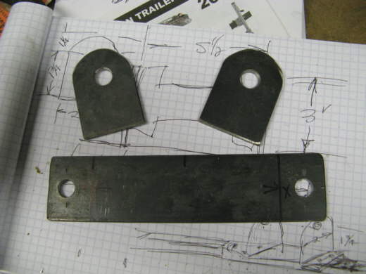
Two tabs were made to go with the strap that we drilled in the picture above at the same time as the rectangular tubing.
..............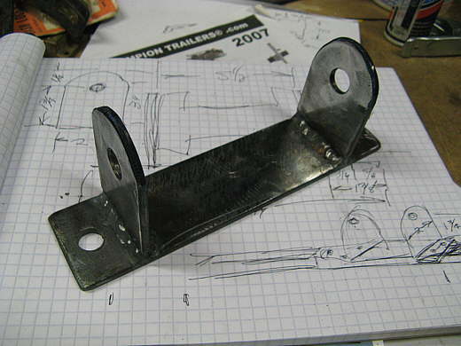
The tabs were welded to the base.
..............
Now we have a bracket for a used roller I had.
..............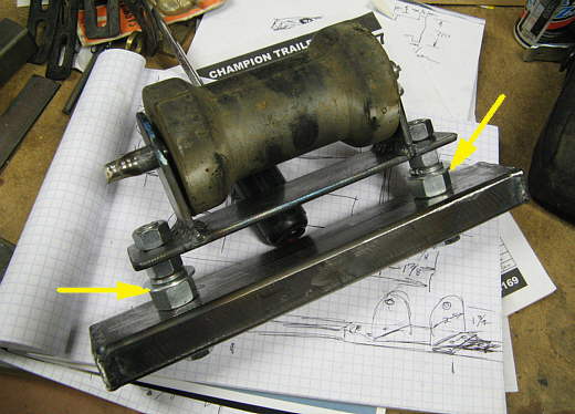
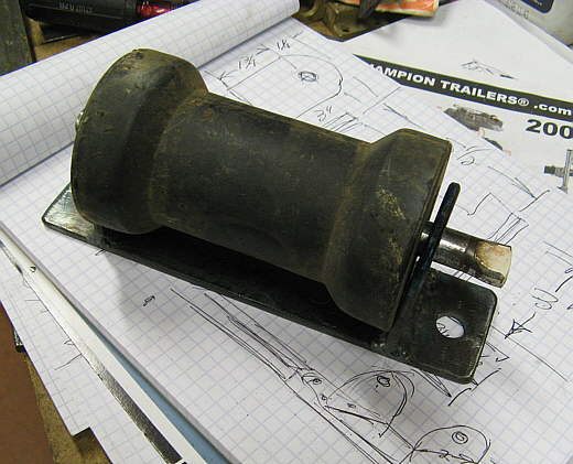
The roller bracket is mounted on the rectangular tube with some large nuts acting as spacers. If the roller ends up later too high or too low I can replace the nuts with different height spacers as needed.
..............
Next the roller assembly was blocked into place where I wanted it behind the axle (left arrow).
..............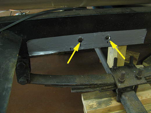
Some tape was put on the frame rails where I wanted holes for bolts to support the new centerboard support. The tape allowed marking the location of the holes easier to see. Two 1/2 inch holes were drilled and elongated a little in the up/down direction. Since the bolts that will go through the holes will be angled down towards the roller support I needed some angled bushings for them to support the bolt head.
..............
Some 1 inch aluminum round stock was drilled out to 17/32 for the 1/2 inch bolts.
..............
Then angle cuts were made to match the angle the bolts would be point down at.
..............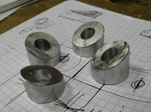
The round stock was cut into these 4 angled bushings.
..............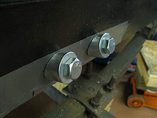
Here you can see how the bushings fit against the frame and give a flat surface for the bolt head to rest on.
..............
A piece of .120 wall 1 inch square tubing was cut with an angle on the roller end and a square cut on the upper end to fit from the roller mount (right arrow) up to the bolt area (left arrow). A piece of strap was drilled with holes the same distance apart as on the frame rails and welded to the end of the square tubing (left arrow). You can also see how the bolt goes through then end of this piece (left arrow again). The same was then done for the other side.
..............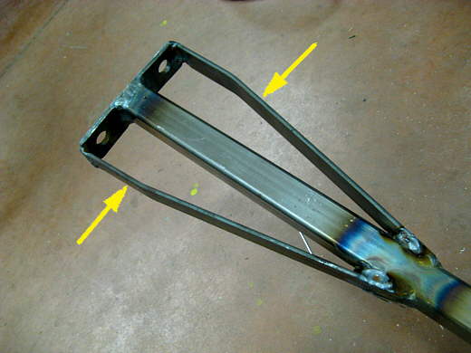
To strengthen the piece the bolts go through the side pieces were added (arrows).
..............
Two pieces of strap were welded to the square tubing at the roller end to reinforce the joint at that point also (arrows).
..............
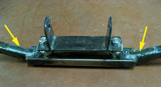
The almost finished centerboard support. I wanted to add some stability to it in the fore/aft direction so this......
..............
.... bar was made and the ends capped off to prevent water from entering and tabs welded on that....
..............
.... allow it to be bolted to the rear bunk crossmember. in the back (right arrow) and the roller assembly in the front (left arrow). Now the roller assemble can't move in any direction.
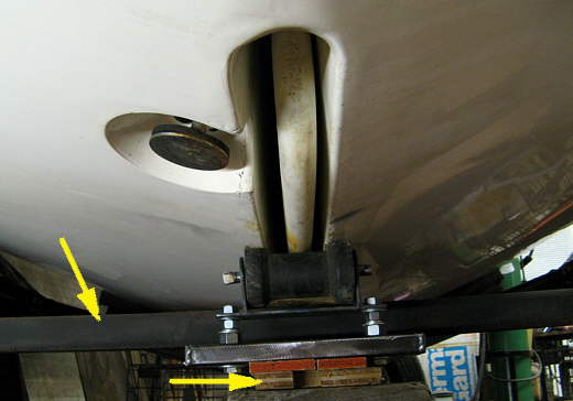
..............
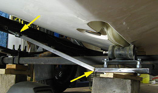
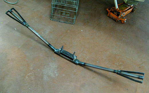
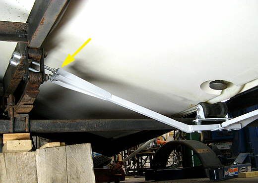
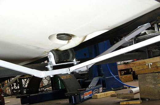
Here is the whole assembly in place with the centerboard (arrow) resting on the roller and the roller barely under the bottom of the hull. I have one nut and two washers as spacers under the roller on both sides.
..............
Here the whole works has been painted (hope to have the whole trailer white at some point). You can also see how the bolts hold the one end. There is a nut on both sides of the bracket along with a lock washer...............and..........
..............
....... one final view.