..................
.......................--- Outboard Hoist for Dingy & Mac ---
..............................--- New Mast Support & Roller ---
I wanted to be able to lift our main outboard on and off the transom and/or lift the dingy outboard onto it's mount at the back of the pushpit either on or off the water. On this page I'll show the process of making a simple hoist to accomplish that.
...............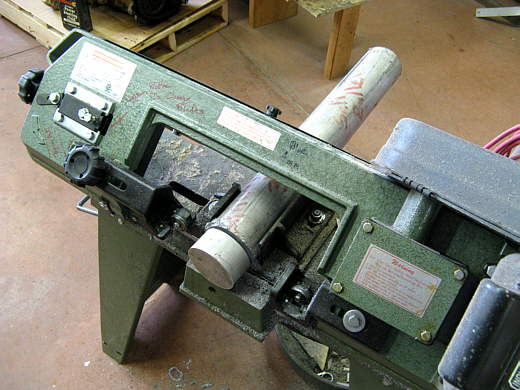
First item of business was making a couple pulleys for a wire rope to go over. Using a band saw a piece was cut from the end of some scrape that I had bought.
...............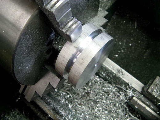
It was chucked up in the lath and the center was cut where the wire rope will ride.
...............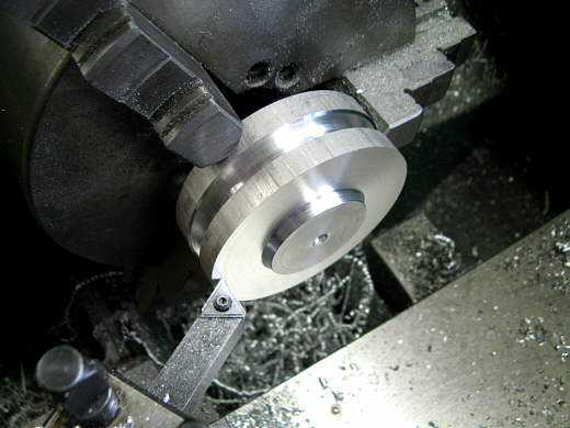
The ends were then faced in and ...........
...............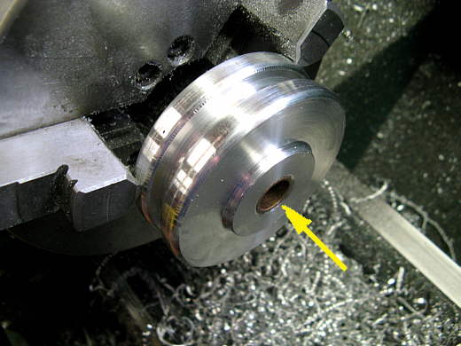
.... the centers were bored out for a bushing (arrow).
...............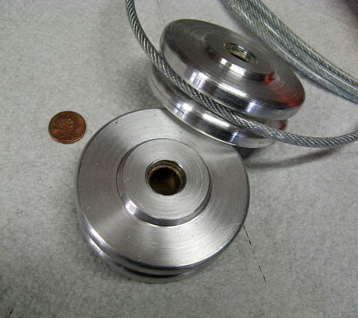
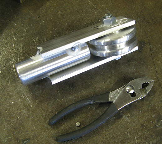
Here are the two finished pulleys. The wire rope is encased in a covering.
...............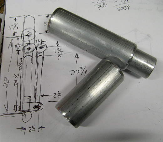
This next part gets a little complicated to visualize. Besides being a hoist this assembly will also have a roller at the top to support the mast while the boat is on the trailer. My shop has two sides to it and one side has a high doorway and the storage side has a low doorway. I wanted to be able to remove part of this stanchion easily so that I could back the boat through the low doorway for winter storage. To do this the upright has some different length sleeves in it to both provide strength and to make it removable. The upper picture shows some of the sleeves laying on a drawing of what I'm making.
...............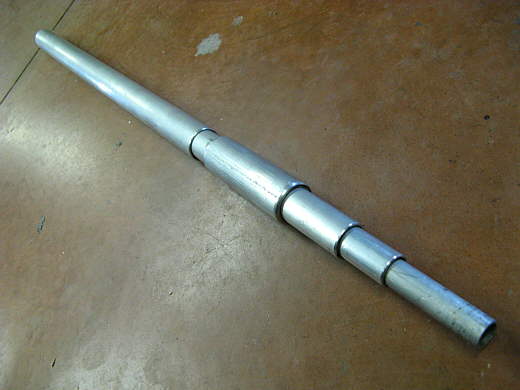
Here you can see the different pieces that make up the upright.
...............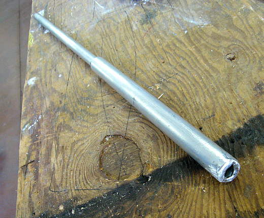
Some of these were welded together. Again the aluminum tubing that I could get here was a thin wall and if I could of gotten a thick wall tube some of this wouldn't of been necessary.
...............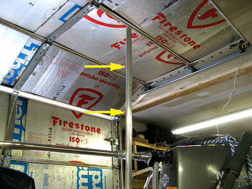
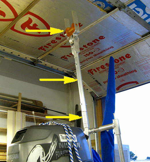
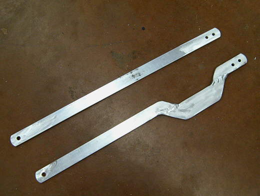
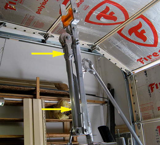
The lower part of the upright was bolted to a bracket down on the transom (not shown). Up at the rail the upright was welded to a piece of tubing that slides onto the top rail of the pushpit (below arrows). The bottom arrow points to the part that will stay on the boat and fit under the shop doorway. The upper part (top arrow) can stay on with the rest of what will be made and will fit under the high shop door.
...............
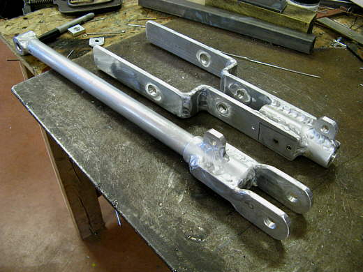
Next this top piece was made that will go on the top of the upright and holds the top hoist pulley.
...............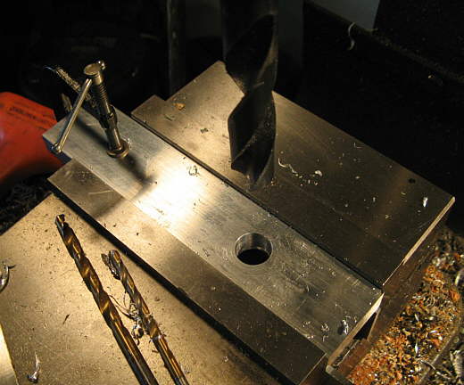
These two pieces (clamped together) are being drilled for the mast roller.
...............
They were then welded to the piece in the previous picture using two shorter horizontal pieces. The other piece was also finished welded.
...............
Here is the upright finished top to bottom. The two bottom arrows point to tubing that slides over the main upright piece.
...............
This is a piece that was made that ...................
...............
.... supports (triangulates) the upright from side to side and is permanently attached to .....
...............
...... the pushpit top rail with this bracket.
...............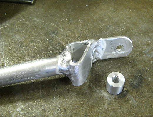
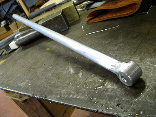
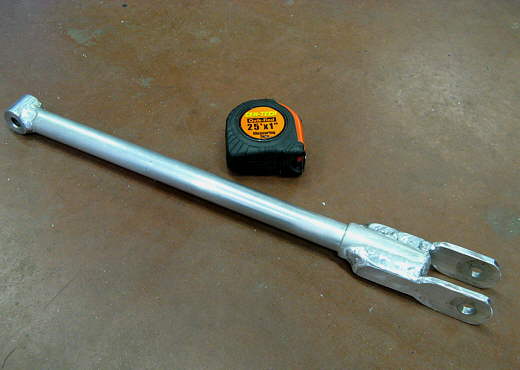
While the mast is on the roller or when hoisting with the upright I wanted to add a support that would located the upright fore and aft. I made a bracket and welded it onto the end of a piece of tubing and also made a spacer to mount it to the upright.
...............
I used the old mast support brackets that were down in the cockpit and made this piece that will be the bottom of the removable support out of a piece of wood and some aluminum. The top piece that is bolted to the wood was then welded onto.............
...............
the bottom of the tubing and at the same time I redid the other end slightly into a boxed in shape with a hole in the middle where it will bolt to the upright using the spacer.
...............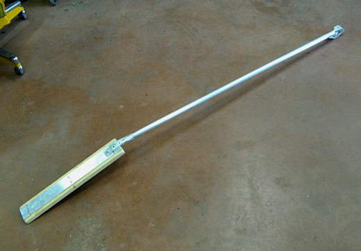
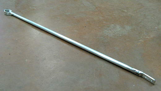
Here is the finished brace.
...............
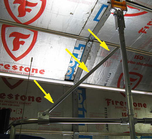
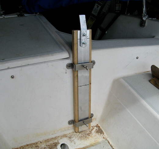
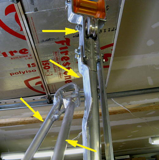
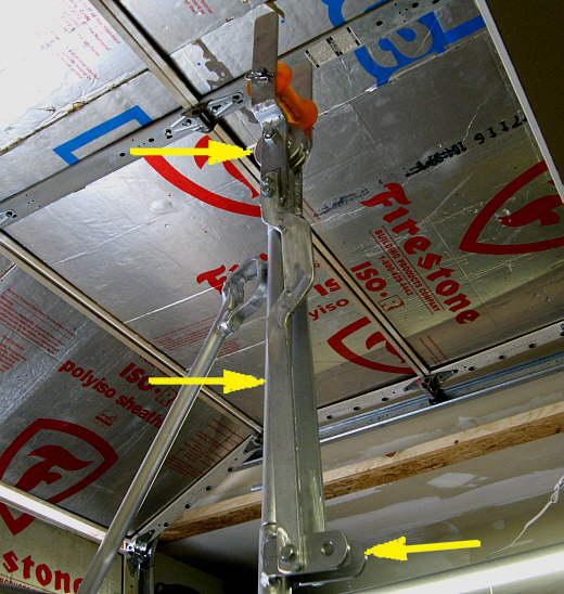
It slides into the two brackets down on the cockpit (bottom arrow) and the thumb screws there are screwed against it. At the top there is a bolt that goes through the upright and then through the space and then through the hole in the top of the support and has a nut on it. To remove the brace while on the water you remove the one nut at the top and loosen the two thumb screws at the bottom and it comes right off. Less than a minute. It supports the upright fore/aft (top left arrow) and the top right arrow points to the side brace for the upright that supports it side to side.
...............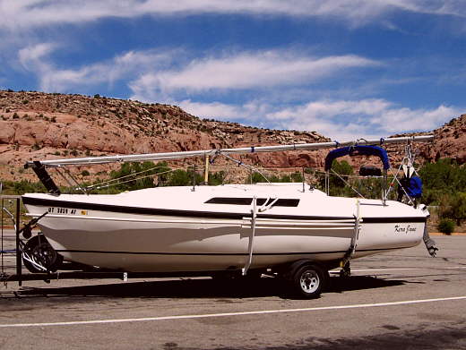
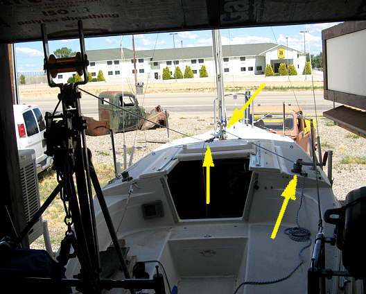
The new mast support at the rear moves the mast nice and high while the Mac is on the trailer. It clears the bimini fine and it is a lot easier to get in and out of the cabin while the boat is on the trailer and since we sleep in the boat on trips this is important. Being able to have the bimini in this vertical position also helps when boarding the boat on the trailer as it is easy to step down into the cockpit and pass under it.
For now I have a wood support that supports the mast at the location the mast attaches to the top of the cabin when it is up. It is visible in the picture above. It keeps the mast from flexing while on the trailer in the stored position.
...............
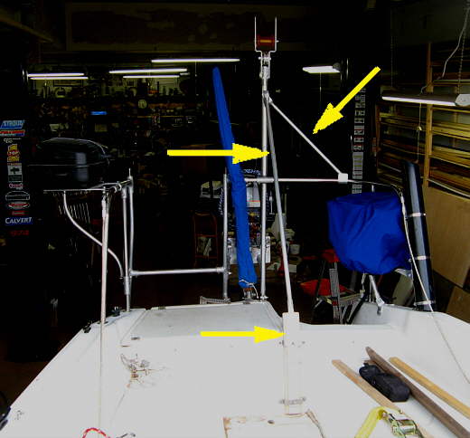
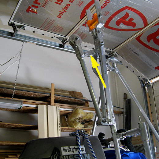
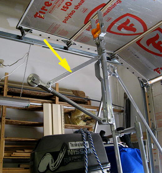
The bottom left arrow points to the removable brace that goes down into the cockpit. The bottom right arrow points to the side brace. The hoist has to be able to rotate to remove the outboard off the transom, so the middle arrow points to a bracket that is made in such a way to clear the supports when this assembly is rotated. The hoist assembly rotates on the center upright support tube at the top and..............
...............
..... further down is a second bracket that rotates on the inner upright (arrow).
...............
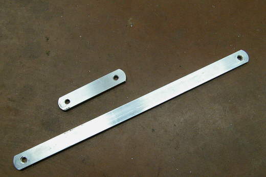
These are the two pieces that connect the lower bracket to the upper one, so that they rotate together and they will be used for something else also shortly.
...............
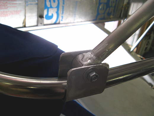
Here you can see how the long brackets attach the upper pivot piece to the lower one.
...............
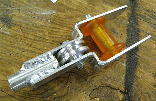
This boom arm was made next and ............
...............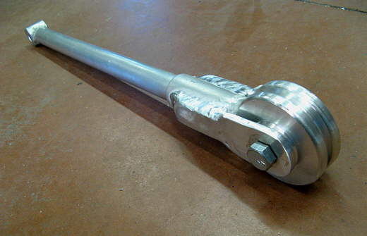
....... the other pulley that was made at the top of the page was attached to it.
...............
The boom was then attached to the lower bracket. Now it will also rotate and stay aligned with the top pulley.
...............
A bracket was welded to the top piece and another to the boom piece (the two tabs).
...............
These two pieces were made that will either locate the boom in tight to the upright or further out.
...............
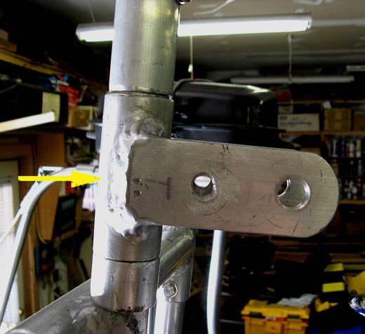
They bolt on where the arrow is. In this picture the short one is bolted on and....
...............
.... in this picture the long one is bolted on. The short one is always there and so far I haven't found a need for the long one. The boom is high enough and the line to the outboard is long enough that you can just pull the outboard out or side to side enough to move it where you need it.
...............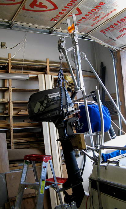
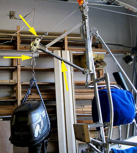
Here you can see the hoist lifting the dingy 5 HP Nissan off of its stern mount.
...............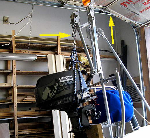
The top right arrow points to the coated wire cable that runs from above the carabiner (left arrow) up over the two pulleys and forward on the boat.
...............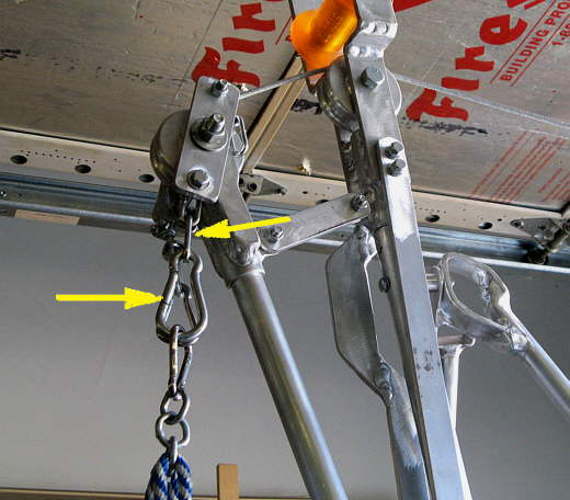
This close up shows that if you want you can take the motor up and clip the carabiner on two chain links and remove the hoist line (wire cable) and then attach the cable to the boom and lower it with the outboard down to where you can put the longer support brace on if you want the motor hanging further off the boat. With it now further out you can reattach the cable to the outboard and lower or lift it further away from the boat. So far that hasn't been needed. It sounds complicated, but can be done in just a couple minutes.
...............
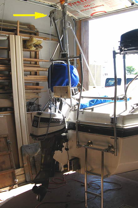
To work the hoist we use the block and tackle that is used to raise the mast. The block and tackle is attached to the bail at the bottom of the mast (upper center arrow). The wire cable is attached to one end of the tackle (bottom left arrow). The other end of the line from the block goes to the winch (right arrow).
...............
A close up of the block and tackle. Using the winch Ruth can easily raise or lower the outboards while I guide them. You can also do this by yourself.
...............
Here the boom has been placed in the out position that I haven't really found to be necessary.
...............
Here I have lowered the dingy outboard down to the shop floor.
...............
Here the hoist has been rotated to the side to raise the boats Honda outboard onto or off the transom. As I write this I'm 65 and have had two hernia operations and don't want any more. The hoist only takes a couple minutes to set up and there is no more straining moving these outboards on and off the boat.