..................
......................................................................--- Boat Fridge Build Part III ---
..............
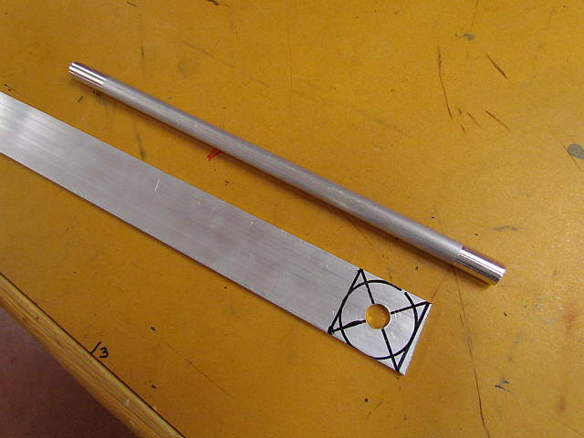
Next a drain was made for the bottom of the box from more aluminum.
..............
The finished drain along with a plug for the drain that was made on the lathe.
..............
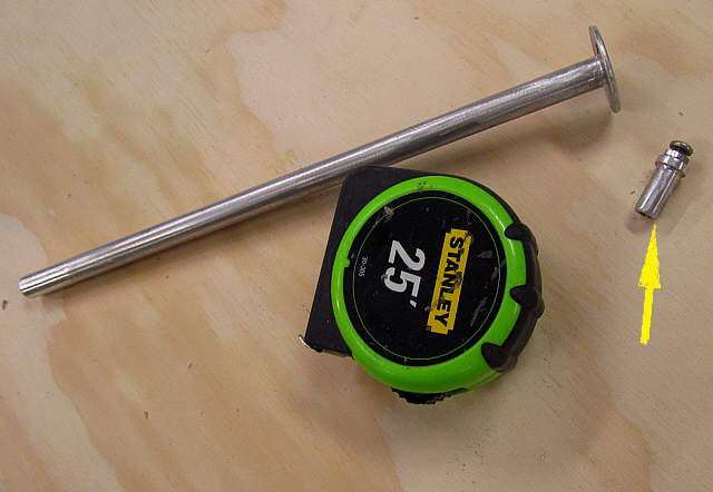
The purpose of the screw in the top of the plug is to just have something to grab to pull it out and a small chain could be attached to it if needed.
..............
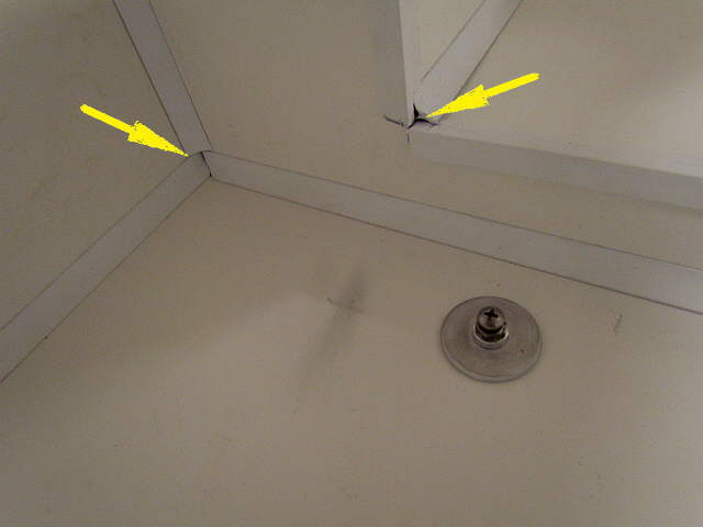
The plug and drain in place. I had to weld up a rod on a bit to get it long enough to drill through all of the insulation. The arrow points to gaps in the molding that were sealed on the boat with caulk.
..............
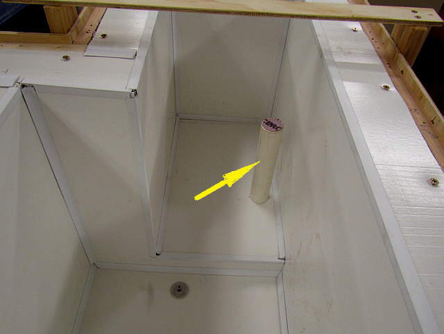
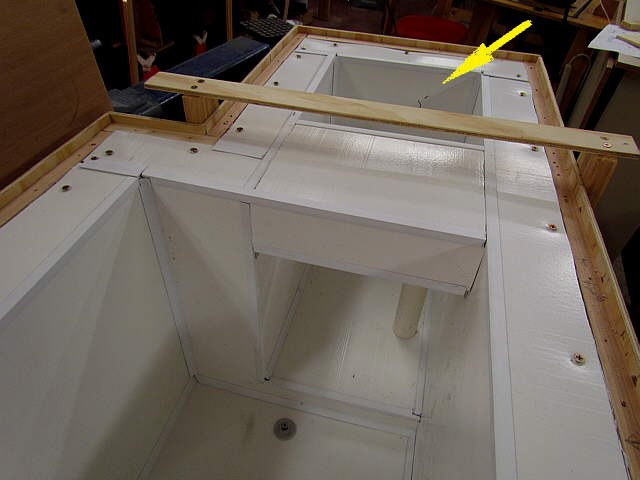
A hole was drilled in the small side of the box and a piece of PVC inserted in it. The line for the coolant from the compressor to the evaporator will go through it along with the thermostat control wires. I kept the foam that was drilled out with a hole saw so that after the coolant line and wire was in place I could use them to plug the PVC as shown above. The PVC pipe sticks up for one main reason. Cold air drops and the coldest part of the fridge should be the floor area. The pipe will be plugged, but I wanted the opening where the lines run out to be higher in the box and they couldn't run out through the walls for this install or most installs for that matter.
..............
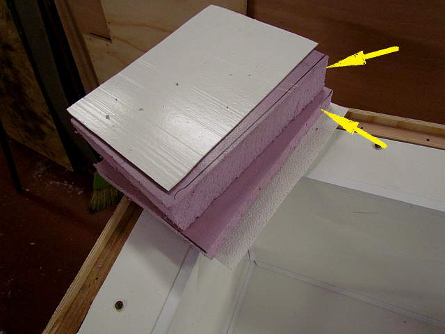
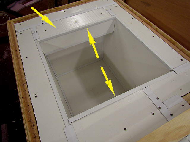
The top of the box will have to openings, one over the large area and a smaller one over the small end of the box. Next top filler pieces will be inserted where the openings won't be. The top fillers consisted of a piece of 1 inch foam and a piece of 2 inch foam, arrow.
..............
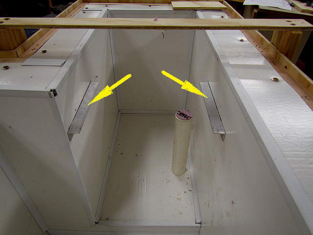
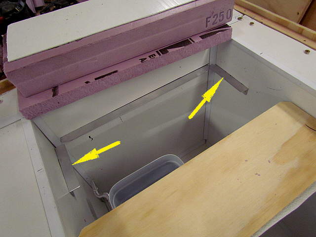
The first filler is being inserted between the small and large sections of the box. Two pieces of aluminum angle were screwed into the box on either side there.
..............
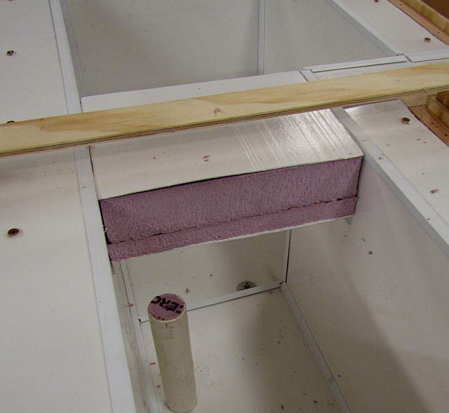
The two pieces of foam with plastic top and bottom rest on the side brackets.
..............
The top and sides were also covered with the plastic. The bottom arrow points to the foam that was saved from the hole for the PVC.
..............
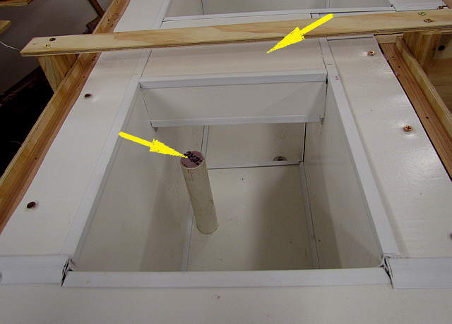
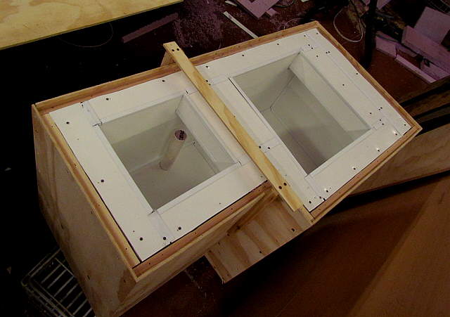
With the filler piece in place we now have the small side opening, arrow.
..............
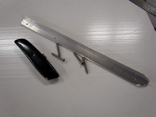
Next brackets were made for the hull side of the box (the knife was there for sense of scale only).
..............
Again the brackets were put in place for the foam...but....
..............
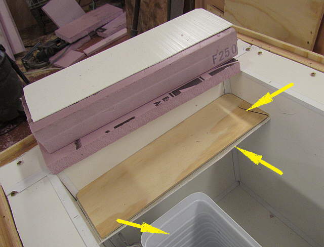
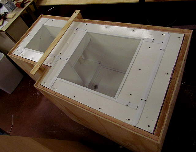
...in this area I also put a piece of plywood on the bottom with plastic under it. Don't ask me why I did it here and not the other location. The bottom arrow points to the evaporator/freezer that I would place in the box to make sure that later I could remove or install it in the future.
..............
This end piece also received plastic on the side and top to cover it. We now have the large side opening into the box, double arrows.
..............
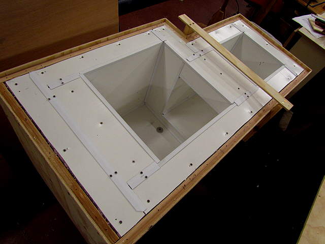
A view of the box at this point.
..............
...notice that the spreader preventer is always in place.
..............
Finally the box is coming together.