..................
...................................................--- V-Berth Make-Over - Part I ---
..............
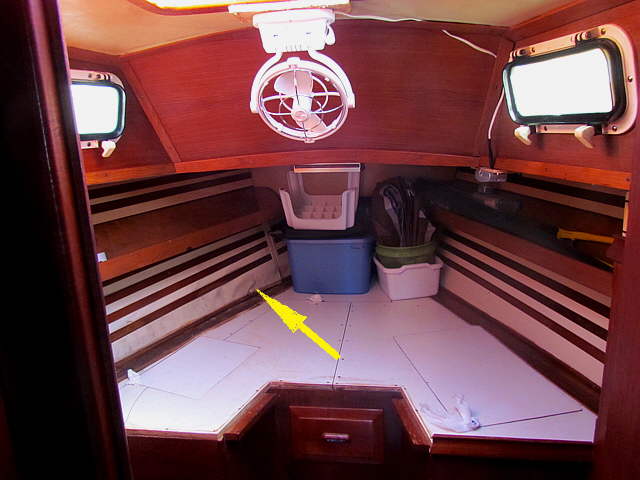
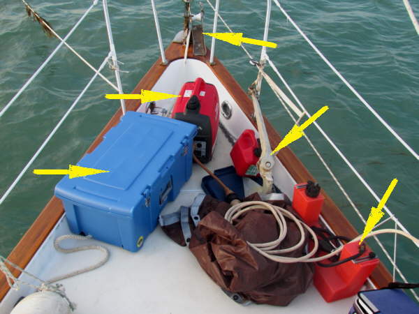
The picture above is of our boat after we bought it and is pretty much how it probably looked when new in 1981 with the exception of wear and tear and damage, arrow, from water intrusion.
..............
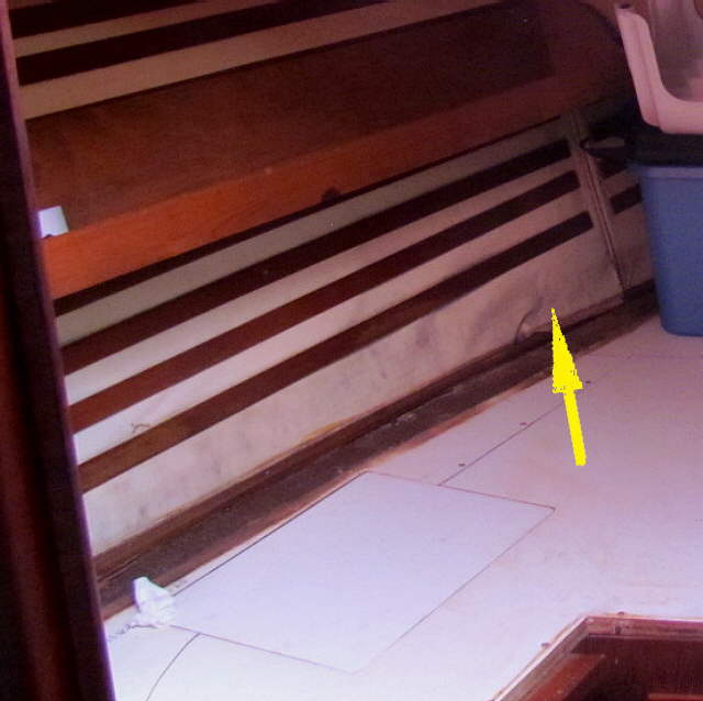
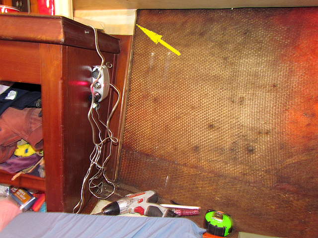
A closer look of the same area. The fabric is wrinkled since the thin plywood that it was glued to has sever water damage. It isn't just in that area. The wood behind the fabric and trim wood was all delaminated along the whole area. The starboard side wasn't as bad, but still not good.
..............
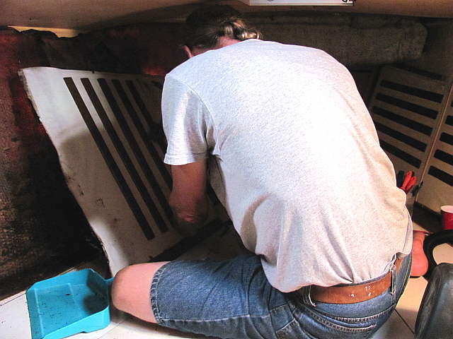
Here I'm ripping it all out which was very easy but messy as the backing just fell apart. The fabric was holding it together not the other way around.
..............
Here I've moved the whole port side back to the locker just off the picture to the left. The bottom arrows point to where the V-berth platform is glassed to the hull. We were lucky and that area was still sound. You can also see the two anchor rode lockers that are in the bow. The top right one shows the one that is molded into the top deck.
..............
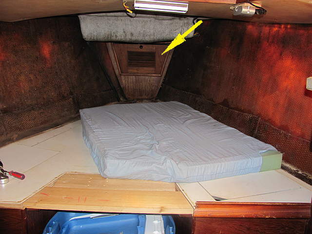
The access to the locker is the hatch just under the Honda generator above that were using while anchored. In that locker is a hawse pipe that allows you to also store a rode below the upper locker in the area forward of the V-berth shown 2 pictures up or where the arrow is in the next picture.
..............
As you can see above all of the starboard side paneling was also removed. It took less than an hour to pull all of this out and throw it away, but I did save all of the long wood trim pieces as they were in good shape.
..............
I cut the old panel where it meat the storage unit. It was solid there and stopping there would simplify putting in the new panels.
..............
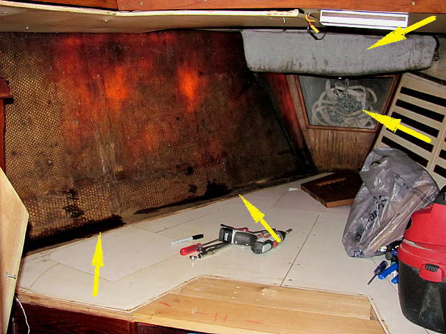
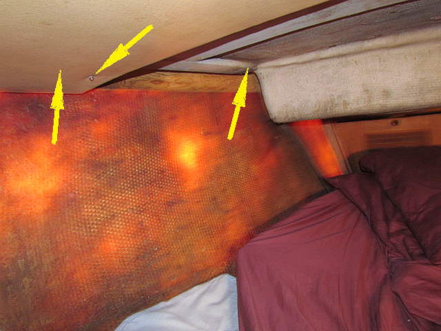
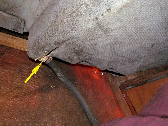
The headliner was removed where the right arrow is and also the headliner that wrapped around the anchor rode locker. I removed some of the screws holding the headliner that is still in the picture, left arrow and rotated it away from the hull and secured it there.
..............
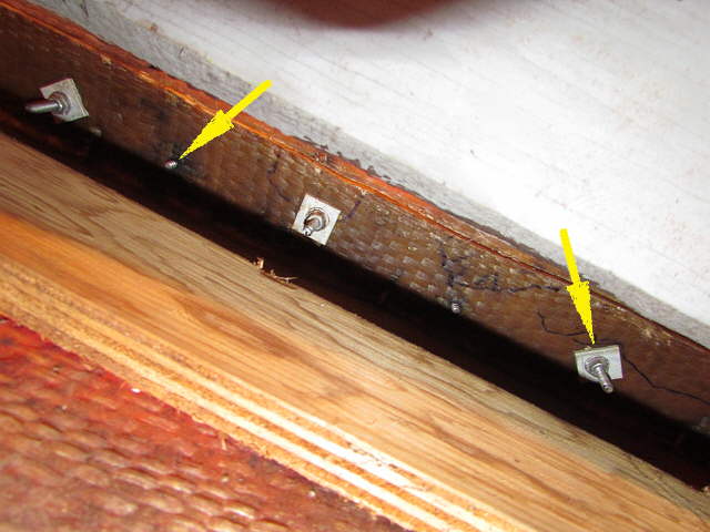
The picture above is shot up along the hull and shows where the deck is bolted to the hull with bolts/nuts, right arrow and with screws, left arrow. Most of the water was coming in along this joint.
..............
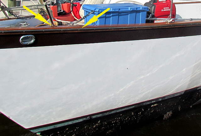
Some water was also coming in from around the bottom of the stanchion, left arrow. There is a metal rub rail along the join line and two pieces of wood. They join just above the metal and you can just barely see the joint where the right arrow is. The caulk in that area was missing or not good. I dug what I could out and re-sealed it with 3M 4000 which I've had really good luck with on the MacGregor.
The V-berth had gotten wet on that side a couple times after we were staying it it, but not every time it rained. I think the wind had to be coming from this side. It never was wet on the starboard side while we had the boat, so don't know if that side had been re-caulked before or not. I plan on digging as much of the old stuff out that I can around the whole boat and put the 4000 in, but didn't have time on this trip.
..............
For a while I thought that maybe this drain for the anchor well was the problem, but it wasn't. It will get a new hose and fitting though. One problem that I did notice is that while we had been gone for about 10 months pine needles had gotten into the well and the hose was clogged. If it rained very hard it looked like it didn't drain fast enough and would get high enough to go down the hawse pipe and then down the hull and finally down into the bilge. I put a screen over the drain area and hope that cures that problem when we are gone. Finally that hose goes down to a thru-hull that is just above the waterline on the port side (see the bottom arrow 2 pictures up).
..............
I needed some way to hold the new panels in place. To do so I cut 1/4 inch plywood, left arrow, that covered the fiberglassed joint between the hull the the berth deck. I did this as I had to screw the piece to the right up next to the hull and didn't want to screw into the fiberglassed joint. Now I would be able to screw it into the 1/4 plywood.
..............
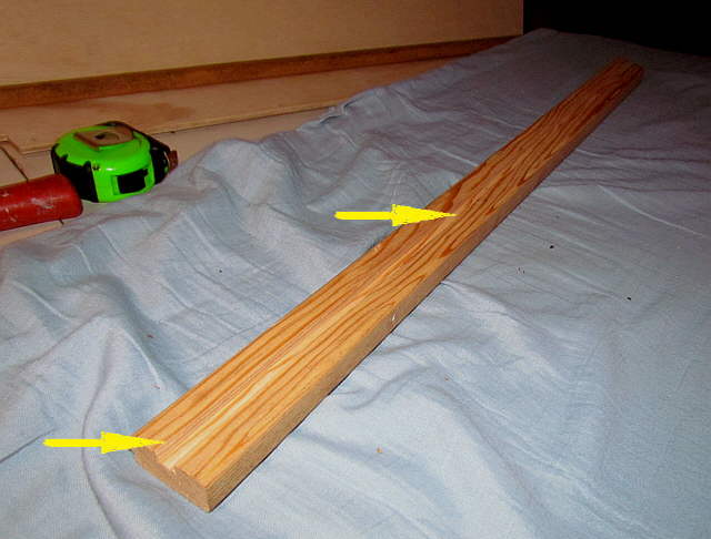
I used the dado blade in the table saw to rip the groove lengthwise in the piece above and others that will run under and capture the side wall panels. You can see one panel in place behind the tape in a similar piece that also has a groove down it.
..............
To the bottom left you can see the longer length of panel in the grooved track and another piece of panel will fit down into the piece above.
..............
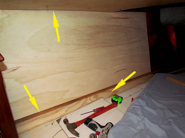
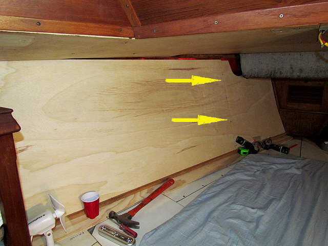
There was enough room to slide the panel up behind the headliner to the left, top arrow. At the bottom the panel is captured by the groove and the grooved piece is screwed to the 1/4 inch plywood which is screwed to the platform. Note that the plywood was cut so as to not hinder removing the hatch where the hammer is lying.
..............
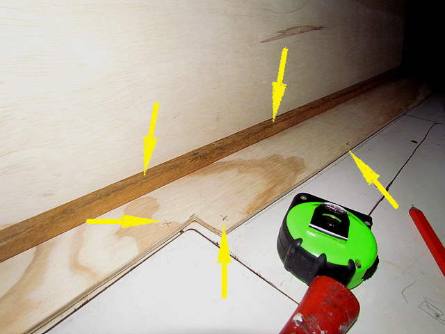
The top arrows represent where the screws will be placed along the length of grooved lumber and the bottom arrows show where the 1/4 plywood will be screwed to the platform.
..............
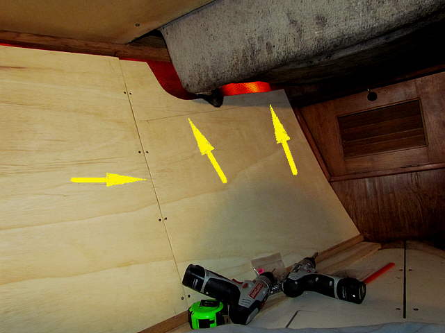
There are two side panels on each side, a long one and a shorter one towards the bow. The arrows show where they are joined by screwing them into a vertical piece of cedar on the backside that is just laying against the hull.
..............
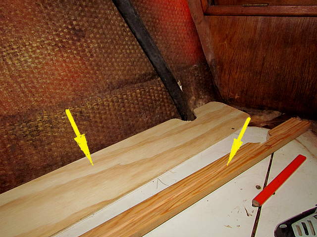
The forward pieces were cut so that they would fit forward against the anchor locker bulkhead and at the top to clear the bottom of the anchor rode locker and the drain hose from it. The two right arrows point to a line that is the bottom of the headliner below the locker. You won't be able to see the panel above that line.