...Return To Mine & Other Bonneville Car Construction Pages
.Previous Page...............B'ville Car Index Page.........................Next Page.
...--- Finishing the Disk Brake Rotor Adapter ---
Before I start into the work on this page I wanted to make a few comments on my thoughts of brakes at B'ville. You need them and I want them, but we have to remember we aren't road racing with these cars and diving into the corners under hard braking. Like on ice or snow, hard braking at B'ville will get you into real trouble. Faster cars with very good streamlining need them more that a stock bodied car that has a lot of drag. Get over 200 mph and brakes aren't going to do you much good. You need a chute to initially slow you down and that is why they require them on cars that can exceed 175 mph. I'll have a chute on this car and hopefully run over 175 at some point. You really just want to touch your brakes at B'ville and let the course and distance you have for run-out slow you down. Don't forget you have 2 miles to stop after a run and then if you don't make that there is still a lot of "nothing" in front of you.
A friend of mine, Hooley, said he just touched the brakes a little after his 219 mph run in his Stude. So I appreciate all of the concern about my brakes from the various people who have taken the time to e-mail me, but I think we will be ok. If not that will be another winter project.
c ya, Sum
............................ .
.
I decided I needed another spacer ring to attach to the adapter I made on
the last page. It would fit the inside diameter of the brake rotor and be the same thickness as the brake rotor.
This way all of the bolt heads on the rotor and the nuts on the adapter would be at the same level and any washers
could overlap the spacer ring and rotor mounting surface (this will be clearer further down the page). I got a
square piece of flat aluminum a little thicker than the rotor and drew an inner circle, to fit over the carrier,
and an outer circle that would fit inside of the rotor. I cut the along the inner and outer circles with a saber
saw a little undersize and a little over size..
................. .
.
I put the sawn piece in the 3 jaw chuck holding it from the center and machined the outside round, but not to final size. Then I held the piece by the outside with the 4 jaw chuck and machined the inside to the right diameter to just fit over the carrier and up against the main adapter plate. Then I placed it back into the 3 jaw chuck and machined the outside to the proper diameter to just fit inside of the disk brake rotor. The last step was to machine it to the same thickness as the brake rotor mounting surface.
................. .
.
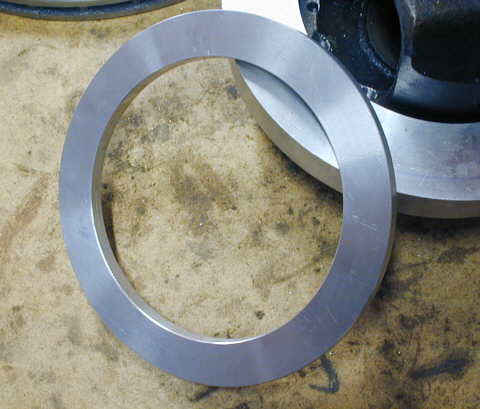
Here is how the finished spacer looks prior to drilling mounting holes into all of these pieces.
................. .
.
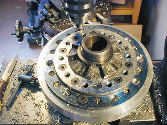
The main adapter and spacer are held to the carrier with 10 - 5/16 pan head bolts/screws (see the one in the foreground hole--similar to the other spacer on the carrier in this picture). The main adapter is threaded for these with a slight counter relief just the other side of the carrier flange. The spacer has 5/16 inch holes in it. So the bolts are counter-sunk into the carrier flange (see holes above that don't have chips in them on the right side). They screw all the way into and through the main adapter. The spacer then slides on them and is held on with nylon lock nuts which also help to keep the bolts from backing out of the main adapter. In the picture above I'm drilling the holes through the carrier, main adapter and spacer. I marked off my 10 holes (the other 10 holes held the ring gear to the carrier), then I would locate the punch mark of one hole with a center drill and drill a small starting hole. Then without moving the table on the mill I would put in the proper bit for a 5/16 tap and drill through the carrier, main adapter and spacer, still without moving the table I would change to a 5/16 bit and drill through the carrier and about 1/16 of an inch into the main adapter. Next I would take the counter sink and counter sink the hole for the bolt head into the carrier. After I did that with all the holes I dropped the spacer down and away and tapped all of the holes for 5/16 bolts. Then I took everything out of the vice and drilled the spacer holes out to 5/16. A lot of changes with the drill chuck!!
In addition I was also going to use all of the original holes on the carrier flange by putting bolts through the adapter and screwing them into the original holes after I tapped them. I then thought that since the rotor is held on with 8 - 5/16 inch bolts that 10 - 5/16 inch bolts to hold the adapter would be adequate. I know they are on a little smaller bolt hole center, but not by much and there are two more.
..............................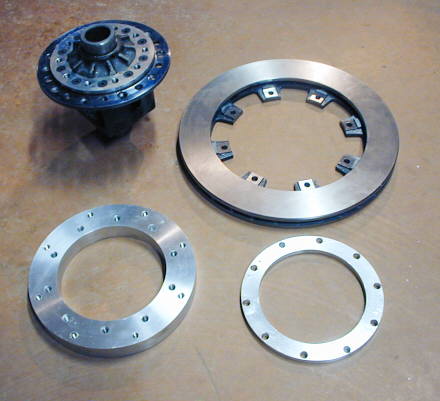
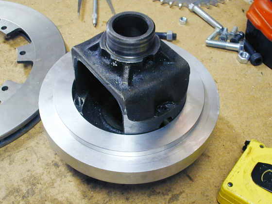
Here are all of the pieces I've made so far. Top left is the carrier that I machined flat on the sprocket side. A spacer attached to the carrier to space the sprocket out from the flange on the carrier for chain clearance. Bottom left the the main adapter plate with the holes to mount it to the carrier and also the tapped holes in it where the rotor is attached. Bottom right the spacer ring with the holes for it to slide over the bolts that go through the carrier and are screwed through the adapter. Top right the disc brake rotor. You can see on it the machined pads to center it on the main adapter. That is why the rotor attaches to the adapter the way it does with that side towards the adapter.
.................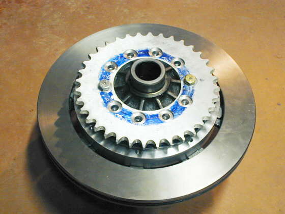
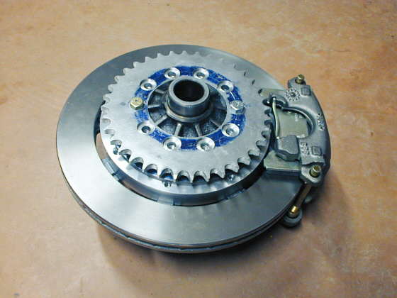
A view of everything mounted from the sprocket side. The sprocket will get 10 aircraft type bolts with holes in the heads for safety wire.
.................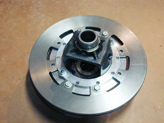
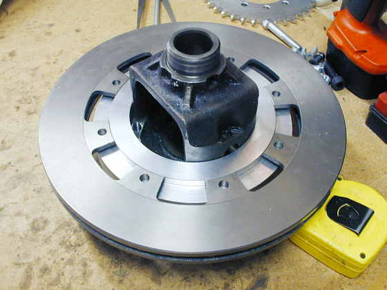
A view of the rotor side. The final bolts that hold the rotor to the adapter will also be aircraft type bolts with holes in the heads for safety wire. The nuts that will hold the spacer to the adapter will be lock nuts.
.................
A view from the top. There will be a chain guard over the chain and sprocket to help keep chain lubricant off of the rotor.
.................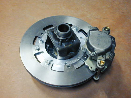
With the caliper in place (kind of).
.................
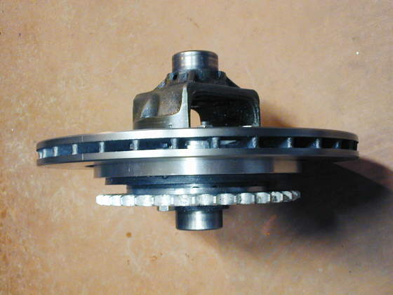
From the other side. The next step will probably be to make the pillow boxes that will hold the bearings that go on both ends of the carrier. The pillow boxes will also give me a place to attach this whole assembly to the frame.
..................................................................Next Page