...Return To Mine & Other Bonneville Car Construction Pages
.Previous Page...............B'ville Car Index Page.........................Next Page.
........................T--- Floor Press & Motor Stand ---
.................
.
I said I was going to make the rotor adapter next, but I got side-tracked. Benny, my crew chief at large who lives
in Texas, is sending me a rotary table for my mill. That will help a lot if I can figure out how to use it. While
waiting for it I decided to make a floor press out of some metal I have. I need it to press the bearings in and
out of the outer hubs and also to press the new ball bearings onto the center carrier.
Here is a picture of the press finished. I'm sure I'll modify it and make plates and punches for it as the need arises.
......
.
.
.
.
.
.
..........
.
I bought a couple springs for $7.00 each and the rest of the metal I had laying around. I drilled hole 1 1/2 inches apart up and down the vertical side supports so I could move the bottom table up or down as needed.
The rest is pretty evident. It seems to work well so far. This is also the jack I use on the PRESS BRAKE I made a few years ago.
.
.
.
.
.
.
.
.
................. .
.
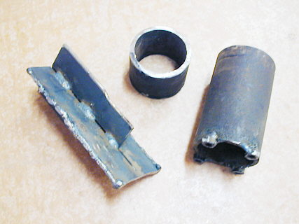
Here are 3 pieces I made to push the bearings in and out of the outer hub. The one on the left goes into the hub and pushes the bearing out by the outer race. If you look at the bottom of it you can see I welded onto the outside of it and ground the inside bottom of it a little so I would only be pushing on the outer race.
The one on the right pushes the bearing back into the hub. I welded the 4 nuts onto it so that it would be pushing on the outer race only.
The middle one is used to push the axle/spindle back into the hub and into the two hub bearings.
................. .
.
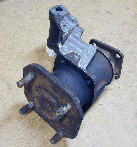
Here is the the outer hub I machined earlier with the axle/spindle pressed back in using the floor press. For years I've used punches and the vise on bearings (not good) and u-joints, etc. I can see I should have built or bought a floor press long ago.
.
.
.
.
.
.
.
.
.
.
............... ............
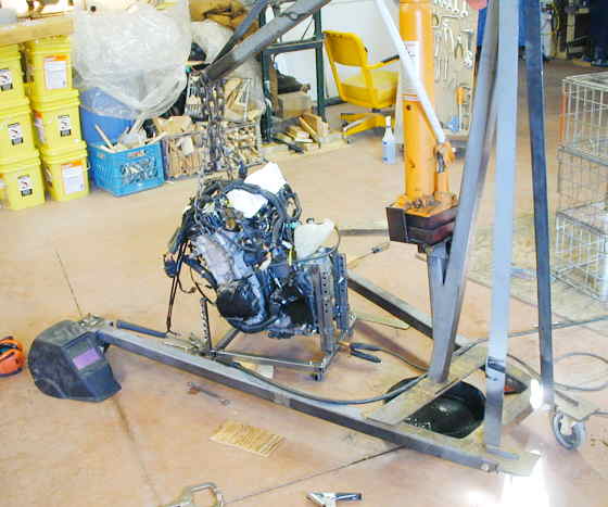
For the past couple months the Suzuki 750cc motor I bought has been just sitting on the floor in the shop. I wanted to build a stand for it to roll it around. I started out to just throw together something with wheels on it, but then thought if it held the motor in the right position horizontally and vertically and was adjustable to height off of the floor I could use it to position the motor in the final car as I mock it up.
..............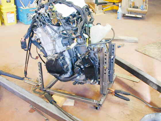
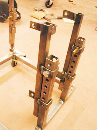
I made some rear mounts for both sides of the rear with one piece that bolted to the motor mounts. I welded some short pieces of larger square tubing to those pieces. I welded uprights with holes in them to the frame. The holes are at one inch intervals and allow me to set the final height of the motor.
..............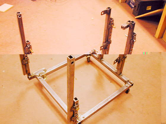
I made the front mounts similar to the rear mounts. All four mounts are removable one at a time. I hope to position the motor where I want it in the frame and then weld mounts off of the frame one piece at a time until I've replaced all of the mounts on the stand with the permanent mounts in the frame.
.............. .
.
.
.
.
.
This picture shows the way I made the mounts a little better.
.
.
.
.
.
.
..............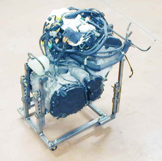
Here is the final stand with the engine sitting about the distance I envision it sitting in the final car. There is about 3 inches of ground clearance between the lowest part of the motor and the ground.
..............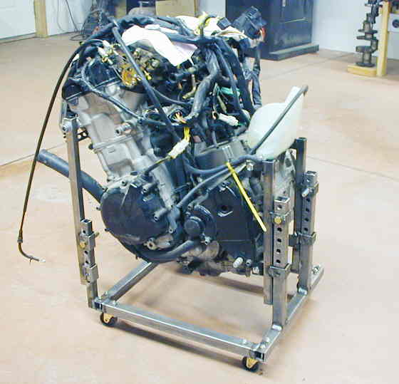
The centerline of the countershaft sprocket on this side is about an inch or so above the centerline of the rear carrier where the rear sprocket is located.
Now the next order of business is to try and get the center carrier section
done. Hope the UPS guy shows up in a few minutes with the rotary table :-). HE DID!!!!
..................................................................Next Page