...Return To Mine & Other Bonneville Car Construction Pages
.Previous Page...............B'ville Car Index Page.........................Next Page
... No Idler Sprocket -- Move the Rear-end Part I
During the period I was waiting to get the machined sprocket back from being case hardened I received an e-mail from Pete Moran (see way below) who lives on the Island of Man and races a blown 500cc drag bike. His e-mail convinced me that I should also look at running a roller made from nylon or probably a better choice Delrin the trademark name for ACETAL. So now I was at the point that I thought I would also make one out of Delrin and maybe try both.
Next I posted on the landracing.com forum asking others what they thought. Here is a link to the post and replies (good info if you are going to run a chain driven vehicle). The debate over sprocket adjusters vs. roller adjusters can get into a Ford vs. Chevy deal and there have been really fast cars and bike streamliners using both methods. I was looking at the adjuster as my motor and rear-end were both in fixed positions. So along came Tom Burkland and Howard Nafzger with the suggestion of making either the motor or rear-end moveable. I didn't want to make the motor moveable as later there will be a turbo and intercooler attached to it with all the corresponding plumbing. I had looked at moving the rear-end earlier, but couldn't see and easy way to do it and still make it extremely ridged. For the rear Tom suggested shims in between the billow blocks and the brackets that hold them. I looked at that and decide if I made slots in the side brackets and the bottom frame rail the rear could slide back and forth. Since the forces of the motor/chain are trying to pull the rear forward it would be pulled against the shims. Good idea Tom, thanks. So that is where I'm at now. I'll try to adjust the slack out of the chain by moving the rear and make various thickness metal shims to achieve that.
.................... .
.
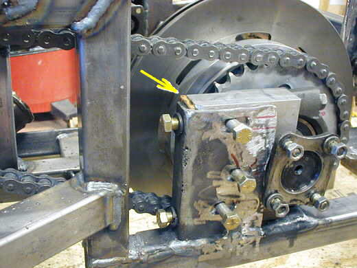
This picture shows what would take place with the idler sprocket (bottom arrow). The chain is in the worst condition here with the most slack in it that it would get before I could remove a link. Just to the left of the left arrow is the counter-shaft sprocket. I can't press down on the bottom run from the middle as it would push the chain towards the shifter shaft, just to the rear of and below the counter-shaft sprocket. This approach would probably work and has worked for others I just didn't like the angles the chain had to run through.
So on to the idea of making the rear-end moveable..........
.................... .
.
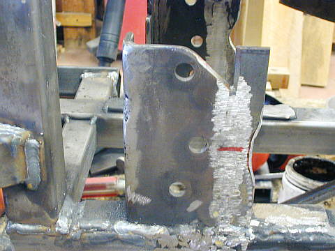
To slot the side bolt holes in the side of the bracket that holds the pillow block I had to lengthen it rear-wards. Since I already had it welded to the frame I had to do all of this in place on the car. I started by welding a piece of 3/16 by 3/4 inch strap to the back end and notched it a little in the middle to clear the output shafts on the rear-end.
.................... ....................
Then I welded in a small triangulated piece at the top to fill that area in. Next I slotted the side plate (after this picture I slotted it about another 1/2 inch). In the picture you can see (arrow) were I inserted a .225 wood shim in the picture at the back of the pillow block. That took all the slack out of the chain that was in the chain 2 pictures up. The final shims will be a combination of aluminum and steel (to be shown later).
.................... .
.
Here is another view. I think this is going to work good. The only other problem this created is that the......
...................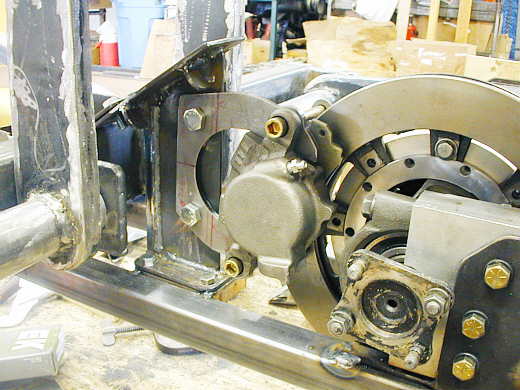
.......rear brake will also have to be moveable so that the pads on the caliper indexed to the brake rotor on the rear-end. I've started on that and will have pictures up probably next week. Hope all of this helps someone else at this point.
Below is Pete Moran's e-mail and other quotes from the landracing.com thread on this subject. Also included in this are ideas and personal preferences on chain types, which I've wondered about. Enjoy and remember what works in one application might not be good for another, so only you can make the final decision on what is best for you.
Pete Moran's e-mail:
Hi fella, well done, I love the detail in you explanations and howl with delight
at your methods. I may be able to help with your chain idler, from experience learnt the only way - hard. I race
a supercharged 500cc single in drag and sprint, I built my chassis and modified or built every other bit; the thing
about powerful singles is the chain gives the tyre a massive kick followed by a long pause, whereas a 4 cylinder
gives 4 smaller but evenly spaced kicks. Here's what I learnt:
Chains never snap on the top run ie the bit doing the pulling. They always snap feeding onto the bottom part of
the sprocket and the reason why is the bottom run is slack, and develops a slight sideways waggle which can offer
up to the sprocket on the chain plate rather than the roller and -Ping. Then the end on the sprocket gets a vicious
whiplash in the direction of travel and flails off the top of the sprocket causing quite some damage, it can certainly
cut steel.
You must not run a tight chain. It will not prevent that slack bottom run and will maul the output bearing in the
gearbox.
As you are running a unit engine/gearbox it is sometimes easier to picture the loads as the gearbox sprocket trying
to wind in the rear of the car along the top chain run, and design according.
Now, the tensioner. Be very careful here, if you see a video of a chain under full load you can see the bottom
run is thrown off the drive sprocket in a nice upward catenary fairly near the sprocket, then curves back to meet
the rear sprocket. Sense would suggest the tensioner should be above and near to the driver, and always on the
bottom run. Unfortunately the ideal position is not fixed and varies with revs, bumps and other minor variables.
You cannot find the position, it will always be not quite right, and the problem is having the tensioner in the
wrong position, because it imposes on the chains' natural harmonic and restricts it. This sets off short duration
unstable vibration, including the-to-be-avoided sideways waggle. Further more, it is exceedingly difficult to engineer
a mount for the tensioner that is exactly in line and vertical, to align with the rear sprocket. Once more only
consider a roller, never a sprocket for the job.
Front and rear sprocket alignment must be as good as you can humanly achieve, the point to particularly watch is
the alignment of the bottom of the rear, as this is where the chain must feed onto. Looking at your admirable chassis
construction pics you shouldn't have a problem with rigidity but visualize any possibility for that rear sprocket
to deviate from vertical, which is the obverse of the sideways waggle: the chain is dead straight but the sprocket
can move sideways, not loose mind, more a slight rotation due to mount flexure.
Always on the bottom run. Tensioners on the top run deviate max pull from the straight line and chew the chain,
sap power, maul the gearbox bearings, and expire too quick, no discussion I'm afraid.
So they go on the bottom run. Still not good, any change from full power puts the bottom (slack) run into the driving
run, as the rear wheel is now trying to rev the engine, particularly on gear changes, and all the time on engine
braking; now all the problems mentioned above happen upside down, and a sideways waggle will throw the top run
as it misfeeds onto the gearbox sprocket, as the top run is slack on engine braking.
Seeing as how you can't tension the chain by moving the engine, or the rear, you would have to be extremely lucky
to get the chain length correct for tension, so a tensioner it is. It must be fixed, as a sprung loaded one certainly
takes up the slack, but again imposes restriction on the chains' natural harmonic, and becomes dangerously slack
on overrun, with too much loose chain wanging around the top on engine braking.
My advice is to engineer a wide nylon roller, double bearing as wide as feasible, on a substantial arm that you
can swing up to take up the slack, and lock off, and I mean lock off, with a separate strut rather than tightening
the pivot bolt, as my primary was always pushing the roller down on engine breaking until I strutted it. Don't
bother to profile the roller to the chains' width, it wont like it and prefers to find its own middle. And finally
install a 'catcher' about 3 inches above the middle of the rear
to catch the whiplash should she snap, or better still a top chain guard that extends over the top half of the
rear sprocket. The roller will groove over a few runs, don't let the grooves get deep as that means the rollers
are contacting the tensioner rather than the chain plates , as it rapidly wears the chain, just swap the roller
for a spare and reskim when you are back in that excellent workshop of yours. And all the very best, from over
the Atlantic, clean over Ireland, and straight into the middle of the Irish
sea _ The Isle of Man, where we appreciate original ideas and happily race anything.
Sincerely
Pete Moran
Mike said "I would move the idler to the center of the chain run. Does two things reduces the back bend of the chain and associated friction. Second by moving it to the middle of the run you reduce the load on the idler bearing because the angle of the chain approach is much shallower. As for chains if you use a high quality O ring chain I believe you will find them virtually trouble free. When Jim True ran Jack's red car that Rick now has we used Diamond O ring chain and ran the whole season with the same chain. The idler was in the center of the run. On our streamliner we run high quality O ring chain on the rear and it is virtually trouble free. We've have run well over 200 high power dyno runs on the same chains. I would follow the chain manufacturers recommendation as to chain wear limits and replace them at about half of the recommended service limit."
Kent said "sum don't waist your time with skate board wheels. been there done that. the material is too soft and will melt from the heat. our chains on the twin engine liner turn purple at speeds over 250 we finally went to a pressurized lube system for it. secondly the bearings are good for your mommas skate boards but wont take the loading and violent whipping action of a drive chain. we turned rollers out of delrin cuz it is harder than teflon and they seem to last 2 passes before we replace them. then we press in 4 hi speed un sealed bearings in the roller. I run RK 530 drag race"DR" chain it is the strongest (11,000 tensile strength) available. it has huge flat non dog boned side plates and doesn't stretch like light weight street bike chains. I use clip style links and never had a problem if ya install them correctly."
Note: bak189 has had luck with skate board wheels -- "We have been using for many years with good success a nylon wheel off a skate-board (they have bearings) mounted solid on the down side of the chain (no load side) The chain will wear a groove into it...and in time the wheel will need to be replaced....mount it close to the rear-sprocket"
Kent said "The roller is 2"wide it allows the chain to move around a little we have had chains jump off of idler sprockets and tear up stuff. if your chain is longer than 100 links I guarantee it will jump off that idler. your bearing speed looks good. our pressurized lubber is a 1 qt alum tank that is full of 90wt gear lube and is plumbed to our 100psi nitrogen air shifting tank. when i hit an up shift button it squirts oil onto our guides, yes we also run adjustable guides on the top run to stabilize the chain whip."
"3" diameter on the roller sounds good. I get my materials from McMaster carr. Sure wish they would sponsor me. I built many of vehicles from their shelves."
"adjusting the rear wheel or axle is the easiest. but not the best for vehicle track. we decided to fix the axles and have the chassis computer aligned at the local car alignment shop and slide the twin motor package forward and aft to adjust the drive chain. we wanted the car to go straight and stay straight at all cost and the chain tention was secondary. we didnt want to adjust the chain and then spend the next hour dickin round with the axle to get it 2 track straight. looks like your pretty deep into your design. after you align the chassis I would sugest you set a punch mark or a reference point so you can acurately measure your side to side axle adjustments with a caliper so you can get that axle straight. dont wory, your design has been done in the past and it will work good it will just take some fiddlin with."
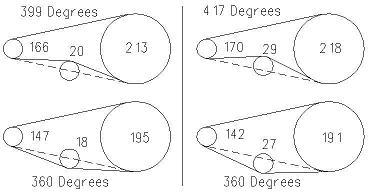
Dean said ".The point I was trying to make earlier was the wrap angle
around the sprockets changes with the position of the idler.
If there is no idler and both sprockets are the same size there is exactly 180 degrees of wrap on both sprockets.
As the drive gear gets smaller there is more wrap on the driven gear and less on the drive gear, but the total
is always 360 degrees of wrap. (Its a circle with straight sections.)
If you look at the picture of the two chains on the left side, the idler is at the centerline of the tangent of
the two sprockets (the dashed line). The idler is at the midpoint between the sprockets. The only difference is
which side the chain wraps. Pushing out modifies the wrap angle for all of the sprockets but still equals 360 degrees.
Pushing in increases the wrap angle for all the sprockets and adds 39 degrees of wrap and friction.
The right two pictures show the idler pushed out/in the same distance. The out angle total stays the same 360 degrees;
the in angle increases the total an extra 57 degrees.
Its true about the oscillations of the chain. Every time the plug fires there is an explosion that sends a shock
wave through the power train that shows up at the chain as a series of pulses. The pulses cause the chain to have
waves of oscillation running through it. The frequency and amplitude vary with speed, sprocket size, distance between
sprockets, etc. High speed video shows the chain looking more like a snake than a straight line. The same holds
for belt drives also. Machinery Handbook under roller chain drive service factors recommends derating the chain
60 percent for internal combustion engines with high shock loads.
If the chain is turning blue it's running out of lubrication and is a huge source of friction loss. Spraying water
will cool the chain, but potentially wash the lubrication off. I wouldn't do it. If the chain is getting lubricated
it won't heat up.
Your idler bearing will take large radial loads but no thrust loads. The chains whipping will generate side loads
that could cause bearing failure. Having two bearings spreads the load out laterally and is better at resisting
thrust loads.
.....................................
Howard said "We used Tsubaki O ringed chain on our first liner and had great luck with it. Our top speed one way was 261.xxx and as a test, we made ten passes on one chain. I did not show significant wear. Don't know what the power was but good enough to go over 260. The chain was lubed with Super Lube after each pass. It was 530 chain. I made the engine adjustable fore and aft to eliminate the need for an idler. Just something else to fail in my opinion."
"I was out in the shop today and checked an old box of chain. We used
Tsubaki Sigma chain on our liner. Maybe that will help if you decide to try it. We used the lube on the chain because
the rep. from Tsubaki told us we should. Probably did not stay on long at the chain speeds."
Mike said "If you use O ring chain you won't wash the lube out if you
cool it with water. We used it on very short chains that were running at surface speeds about 4 times the maximum
recommended speed under very high power. They absolutely would not work with out water. The whole object is to
keep the chain temp below 325 degrees F above which the lubricant begins to break down cooler is better. The O
rings also do not do well at high temps.
For a rear chain of reasonable length you won't need cooling. Putting lube on an O ring chain really does little
good except to keep it from rusting. The outer rollers do not turn when the chain engages and disengages the sprocket.
Only the inner pin and bushing is subjected to rotation and friction. The lube that is vacuum injected when it
is made is all you have to keep the pins and bushings lubricated."
Thanks to all of the guys (above) that contributed some really useful information!!!
..................................................................Next Page