...Return To Mine & Other Bonneville Car Construction Pages
.Previous Page...............B'ville Car Index Page.........................Next Page
........................................... Rear Frame - Part IV
......................
On the left side of the car I started to add some more support to the area where the arm that goes out to the outer a-arm mount attaches to the frame rails. I had put in one piece (below the piece with the hole in it) to help tie the twisting forces to the lower most frame rail. Here I have added the piece with the hole in it to also assist in transferring some of these forces to the lower most frame rail. I will still add a top web to it, but can't go much further with the motor in the way.
.................... .
.
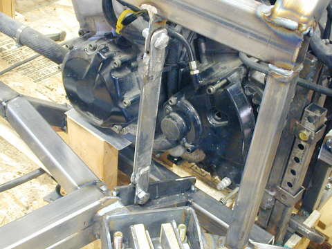
I'll tie the added piece to the top rail with an upright. Here is the start of it, but I think I'm going to re-design this piece. It will get square tubing added to it and also diagonal pieces from the bottom attachment point up to the top rail in front of it and behind it. I'll show that later. I want this piece to be removable to service this side of the motor in the car.
....................... .
.
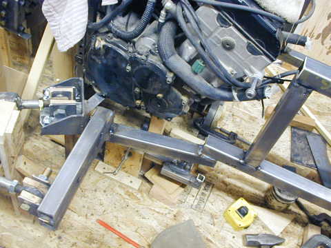
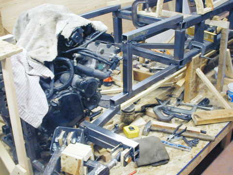
I'll finish the left side of the frame when I have the motor out of the way. Here I started on the right side of the frame and started to extend it back from the cage. The right side will be similar to the left side, but will have differences to clear the motor, which is closer to the side of the car on this side. Here I have the top rail and one of the bottom rails in place along with the out-rigger to the outer a-arm mount to the far left of the picture.
....................... .
.
A close up of the out-rigger to the outer a-arm mount. I'll have the same problem on this side of the car transferring the up and down moments of this arm to the inner frame rails.
....................... .
.
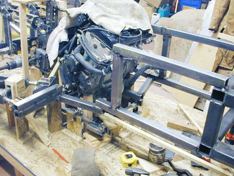
A view looking forward on the car at this point of construction.
........................ .
.
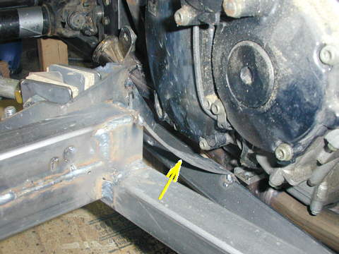
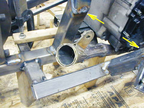
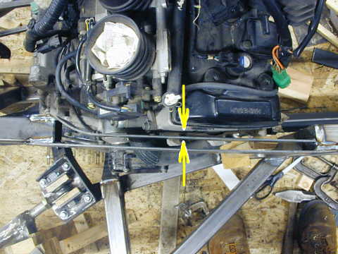
To help transmit the forces on the out-rigger to both lower frame rails I'll build a piece between them. Here I have put in a curved piece that will clear the motor and will attach from the top of the out-rigger to the top of the lower most frame rail. I'll later add a bottom piece from the bottom of the out-rigger to the bottom of the lower most frame rail and then cut and weld in sides, thus boxing all of this in and together.
........................ .
.
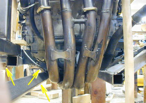
Here you can see the curved piece (middle arrow). I'll make a lower piece that will connect the other two arrows and then make side pieces for that area and weld them all together. This also shows how the stock exhaust will clear the lower most frame rails. The bottom of the car body will hug the two lower frame rails and curve under the exhaust pipes. The exhaust will exit the extreme rear of the car. Later with the turbo there will probably only be a single pipe in this area coming from the turbo that will be in front of the motor.
........................ .
.
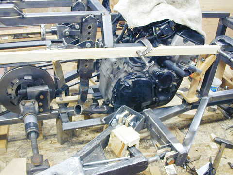
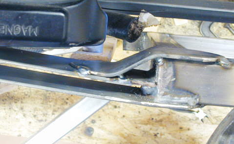
The lower most frame rail goes back under the motor and then ties into the rear frame rail that supports the pillow blocks for the rear end. You can also see at this point I've added a diagonal brace to the out-rigger from the intermediate frame rail.
........................ .
.
The up-right by the left arrow goes up to the spring assembly. The inner a-arm mount (next to right arrow) is attached to the lower most frame rail with a short diagonal piece and there will be another diagonal that will go between the arrows to the vertical spring assembly support. This will all add strength to the inner and outer a-arm mounts. The exhaust also exits through this area and I'll have to add the lower motor mount. There is a lot going on in this area and that is the reason the diagonal will go in later.
........................ .
.
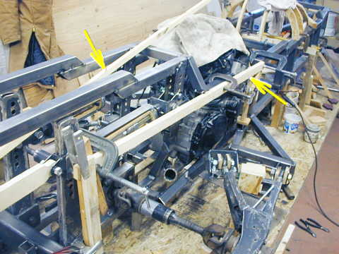
A tricky area developed where the top frame rail goes by the side of the head (right arrow). I finished the top rail in front of that area and then went to the back of the car and built the top rail forward (left arrow to that area.
........................ .
.
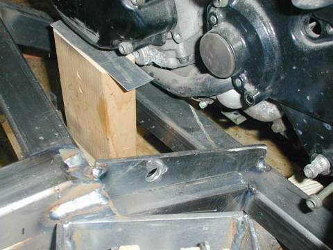
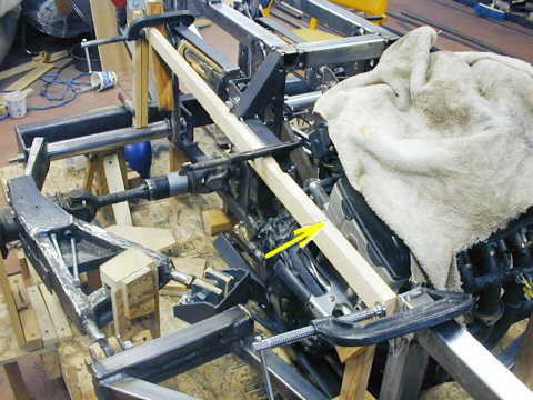
Here (see arrow) is the remaining area of the top rail that has to be closed in. I set up the board and curved it into the back of the car so I could get the angle of the short top rail behind this gap right.
........................ .
.
Then I welded a piece of .120 X 2 inch strap in to form the outer most part of the frame rail. Next I bent a similar piece of strap to form the inner part of the frame rail and spaced the two part apart 1/2 inch with some particle board when I welded the inner piece in.
........................ .
.
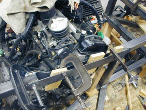
A top view showing the clearance between the top rail and the motor. It will be narrower than the rails ahead of it and behind it, but will be taller in cross section than those rails.
........................ .
.
On the right side I had capped the end of the top frame rail and the new piece was butted to that cap and welded. Next I cut another piece to tie the new part to the inner side of the top frame rail. Latter a piece will be welded to the top and bottom of this section to completely box it in.
.................... .
.
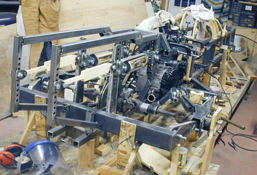
A view of the rear at this point of construction. A lot of pieces at a lot of angles, but it is going pretty good. I'm glad I didn't try and build the frame first and make the rest of the components fit into it.
..................................................................Next Page