...Return To Mine & Other Bonneville Car Construction Pages
.Previous Page...............B'ville Car Index Page.........................Next Page
........................................... Rear Frame - Part I
............
I couldn't go much further on the cockpit without turning it up-side-down to finish the welding so I could put in the diagonal bracing. Before I do that I wanted to finish the rear frame at least so I can make a rotisserie for the completed frame. Being able to rotate the car will help in welding and in making the body.
......... .
.
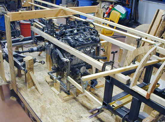
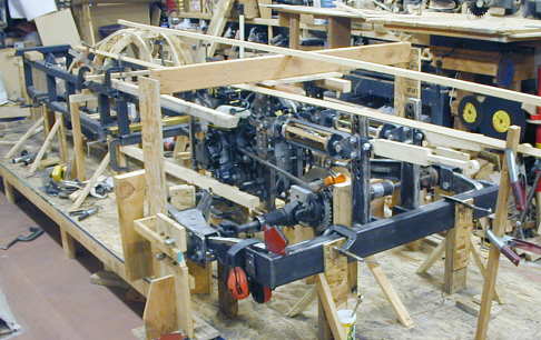
I moved the cockpit ahead about 20 inches to give me more room from in front of the motor to the back of the cockpit. This area will be used by the exhaust headers and eventually the turbo and intercooler and maybe the ice water tank for the intercooler. With the car being so narrow and with the inboard suspension limiting the room on the car I needed this area. I hope it is enough. I hope to have my cooling water and maybe the ice water located in the pods running along the body. I made a board with a 5 inch cut-out in it to represent the 5 inch thickness of these pods. You can see it in the lower right of the picture by the right side control arm. I can move it around the car and see where this area will be.
................. .
.
I also laid out some longer wooden stringers, shown at the top of the picture, that gave me an idea of the body sides along the top of the car as it narrows from the cockpit/motor area to the back of the car. I also put in a couple pieces of 2 X 2's to see where and how I want to snake the frame past the motor.
............................. .
.
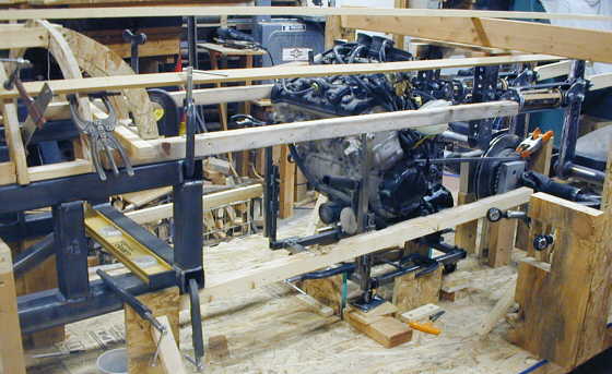
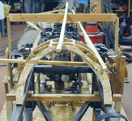
This is a top view of the stringers looking back from the cockpit. The side one is straight, but I hope to make the final body in a curved shape from the motor back to the rear of the car.
.................... .
.
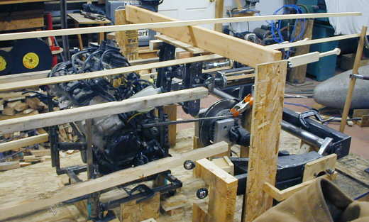
A 3/4's view from the back. It looks as if the total car length is going to be about 18 feet long.
................ .
.
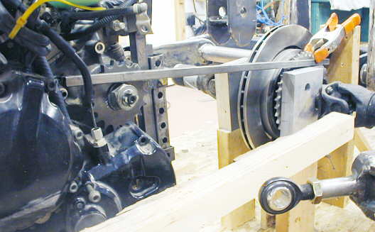
I located the motor at the height I wanted it and the distance I wanted from the rear sprocket. I then aligned it using a straight bar from the rear sprocket to the countershaft sprocket.
.............................. .
.
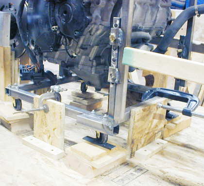
After I had the motor where I wanted it I made 4 stops around the bottom of the motor stand to keep the motor in position during the building of the frame.
............................ .
.
I also made some supports for the rear control arms on both sides of the car that locate it for frame construction. The inner leg of this control arm is within a couple inches of the motor. I needed to make a mount for it that was as small as possible to mount it to the frame. The mount also needs to allow adjustment of the control arm sideways in a horizontal plane to set the toe on the outer hub/wheel/tire and up and down in the vertical plane to set the camber.
.............. .
.
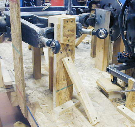
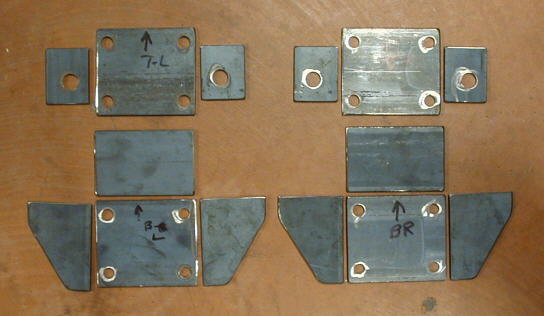
I drew up a couple options, but was having trouble since all of this in/out, up-down movement is happening so close to the motor. I finally came up with a plan and cut out these pieces for the inner control arm mounts for both sides of the car. The outer mount will allow in-out movement, but there won't be a need for up and down movement of the control arm, so it won't be as complicated as what this one is.
................. .
.
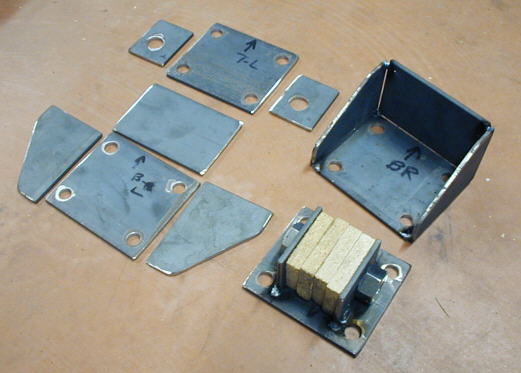
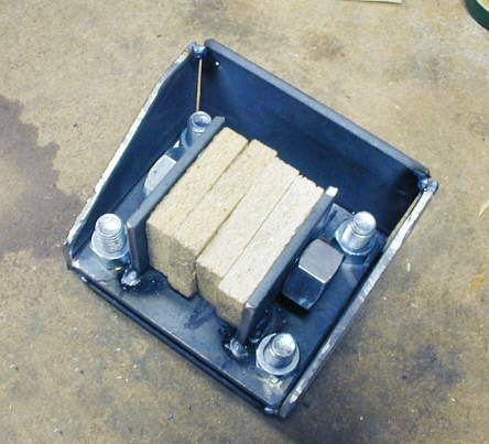
Here I have one side tacked together. The top-right piece will be the fixed bucket welded to the frame. The bottom piece will sit on top of the other piece and the 3/4 inch bolt that is holding the four pieces of particle board will support the rod end on the end of the control arm.
.............................. .
.
The plan is to use a shim pack of different thickness of plate under the moveable top part. In the picture it is sitting on 4 larger nuts. I will start with about a 1/2 inch shim pack under the moveable top part. That will allow me to remove or add shims to set the camber on the wheel/tire, by tilting the "A" arm control arm on the inboard leg of it.
.............................. .
.
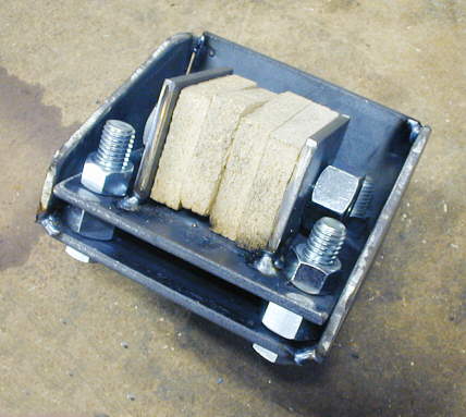
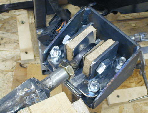
Here is the shim pack made from 3/16 and 1/8 inch strape and .030 aluminun. I have one pack mounted in the mount at the top of the picture.
............................ .
.
The rod end will sit where the two inner pieces of wood are and there will be shims on both sides of the rod end. By moving the shims to one side or the other of the rod end I will be able to set the toe of the rear wheel/tire since the "A" arm will rotate on a horizontal plane.
................... .
.
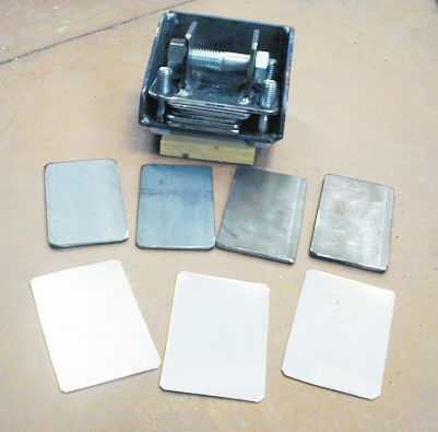
Here is the mount attached to the rod end and blocked into place. The wood on each side of the rod end will be replaced with shims.
................... .
.
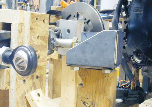
A view from the side showing the rod end on the outboard leg of the "A" arm to the left.
.............. .
.
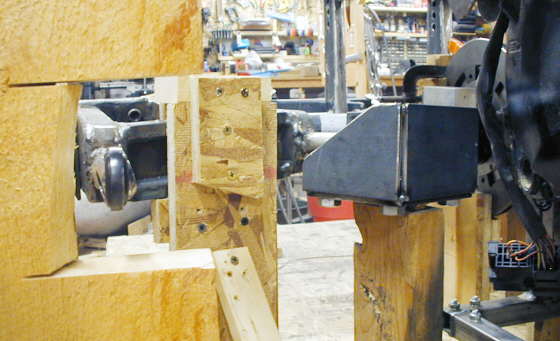
In this view you can see the board I notched out (left side of picture) that represents the thickness of the pod going down the side of the car. The mount I made to the right will also fit into this space. I now need to finish weld the inner mounts and make the outboard ones. I'm getting all of these pieces made and then I'll start making the rear fame to tie the motor, control arms, suspension components, etc. together.
.
..................................................................Next Page