...Return To Mine & Other Bonneville Car Construction Pages
.Previous Page...............B'ville Car Index Page.........................Next Page
......................................................... -- Sketches --
When people see what I'm doing either in person or on the Internet they often ask if I'm following a set of plans. The answer is not really. I've looked at a number of lakesters and other cars on the salt, but what I'm doing isn't exactly like anything I've seen there. But if I wasn't influenced by what I've seen I probably wouldn't have come up with what I'm doing and it seem like every time you think you have a new idea you later find out that someone else has probably done the same thing.
I get a lot of my ideas falling asleep, laying awake in the middle of the night or laying in bed in the morning or driving on long trips. At those times my mind is the least distracted. Now some of the ideas I get during those moments just turn out to be really impractical to implement, but they get me started in a direction at least. I built a lot of the lakester (also my house, teardrop trailer, 1FATGMC, and other projects) just as I go along with no plans drawn up. Just ideas in my head But sometimes, and more often lately, I try and get some ideas down on paper. This page is some of the sketches I've done just to give you an example. I like using the graph paper where the squares can represent different distances.
............... .
.
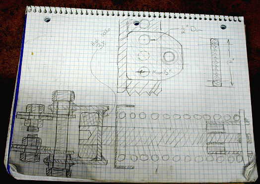
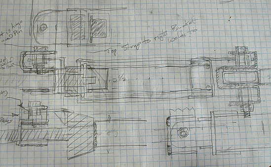
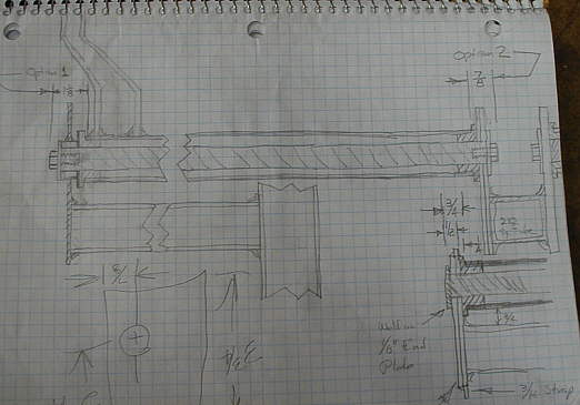
Most of the sketches on this page are of the rear suspension components. The one above is the final one I did before starting the spring assembly. This morning I found out that I goofed and I can't use the one lone pivot bolt on the left side since the jack screw has to move through the area where it is. Usually my sketches help me to avoid these kind of problems. Now I'm going to have to re-make the last 4 brackets over again that took me a couple hours to make in the first place. These things happen.
.................. .
.
Another option for the "lever end" of the spring assembly that I ended up not using.
................. .
.
Another takeoff of the one above that I also didn't use.
................ .
.
This one I did use, although the drawing is not totally finished, but enough to go by to make the part. Usually the final dimensions are dictated by the other parts around the part that I'm making and not necessarily the dimensions on my drawing.
............ .
.
This one was some ideas and also to help me visualize better what is going on with the spring mounted on the lever arm in such a what that the lever arm pulls on the spring, yet still the spring is in compression.
............. .
.
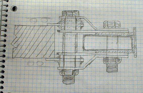
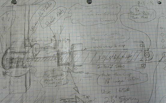
My final drawing of the in-board lever arm before I started to make it. In the bottom right of the drawing I saw that I need 3 holes in the shock bracket and 3 holes in the spring bracket if I want to be able to mount them opposite, above, or below each other.
............. .
.
Another option of how to mount the left side of the spring assembly that would still allow the jack bolt to pass through the upright frame brackets. I vetoed this plan since the left side of the spring assembly would be rigid and couldn't pivot like the right side. That probably would have been all right, but I didn't like it.
............. .
.
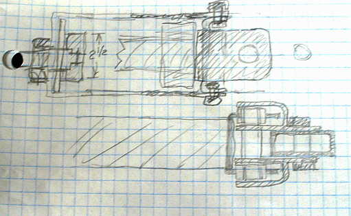
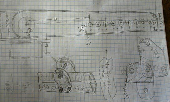
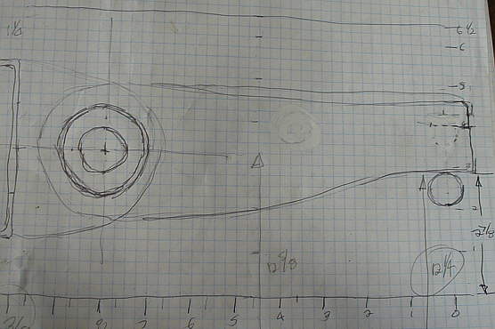
The out-board lever arm that is attached to the tube on the left and rides on the bolt on the hub on the right. This gave me an idea of how tall the tip of the lever arm could be on the right side.
.................. .
.
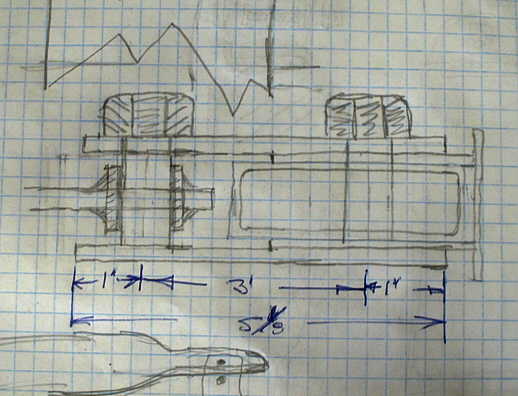
The tube that connects the in-board and out-board lever arms and ideas for supporting the tube on both ends. This shows the out-board lever arm with two bends in it. I ended up with only part of a bend on one side of it and the lever arm welded to the tube at an angle.
....................... .
.
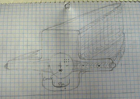
I did this sketch a couple years ago when I was going to build a lakester with a small block chevy and it shows the crank and pan location in the body. Of course this is a sectional view, but is still close to what I'll be doing now. Notice the side pods/fairings that will cover the axles/control arms and suspension parts.
Well I probably won't post any more sketches, but I did want to comment some on the process I use to go from thought to product. Most of the time I'm just build the most critical parts and getting them into place and connecting the dots between them. This is true whether it is the over all car or a sub-assembly on it.
c ya, Sum
..................................................................Next Page