...Return To Mine & Other Bonneville Car Construction Pages
.Previous Page...............B'ville Car Index Page.........................Next Page
............. Rear Spring & Shock Mounting - Part II
.........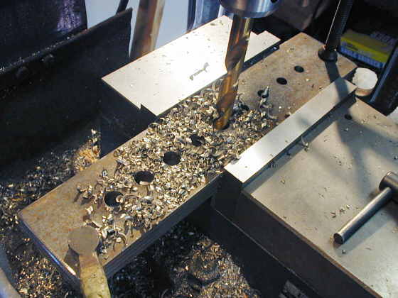
I cut 4 pieces of 3/16 inch strap the same length and put 9 holes in them 1 inch apart to match the spacing of the holes in the lever arm. These will be used to mount the chassis end of the springs to.
.................... .
.
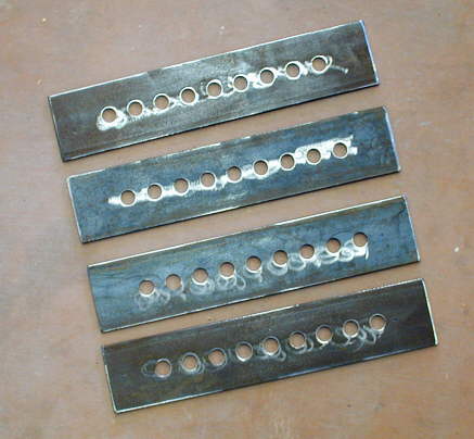
Here are the 4 pieces.
...................... .
.
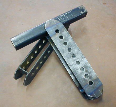
I welded some spacers in the ends to keep the brackets 1 1/2 inches apart. The rear frame members will be .120 X 1 1/2 X 1 1/2 square tubing. These brackets will be welded to the frame members as shown in the mockup above where the piece of square tubing represents the frame.
.......... .
.
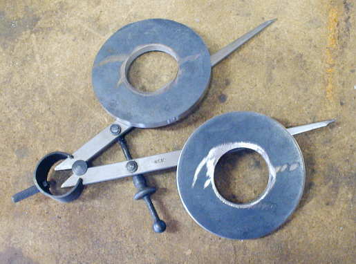
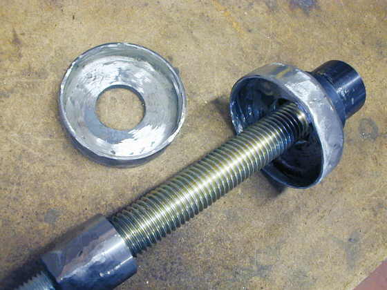
Next I made two washer like pieces, like on the previous page that will be stops for the other end of the coil over springs. I had to bore the centers larger with a boring bar for clearance of the jack bolt that will go through the center of them.
................. .
.
Here they are finished.
............ .
.
I welded 1/8 X 3/4 inch strap around the circumference of the washers to make a spring bucket. This will locate the spring on this end and keep if from riding off the washers.
............ .
.
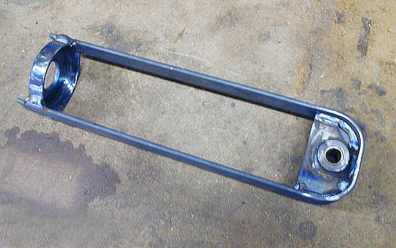
I then welded 3/16 X 1 1/4 inch strap around one of the first pieces I made on the previous page and welded the ends of the strap to the spring bucket I had just made.
............. .
.
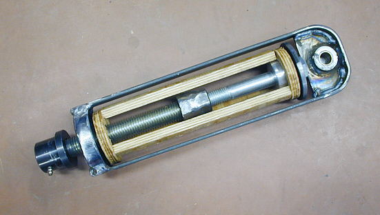
Here I have used some plywood to represent the spring in it's free length (10 inches) inside of the spring holder. The bucket centers the spring on the left end and the aluminum bushing on the bolt in the center of the spring centers the spring on the right side. The inside diameter of the spring is 1 7/8 inches and the outside diameter depends on the spring rate, but is less than 3 inches in diameter. These springs come in spring rates from 80 lb./inch to 550 lb./inch in 15 to 25 lb. increments. To give you an example a 200# spring has an outside dia. of 2.659 inches and a 400# spring's outside dia. is 2.809 inches. The spring bucket above has a 3 inch inside dia. and that is the dia. of the washer that captures the right side of the spring.
Most coil over springs are 2.5 inches ID. I went with these smaller dia. ones to save a little space, about 1 inch in the outside dia. of the spring assembly. They also come in different lengths and I settled on the 10 inch free length as it has about 5 to 6 inches of compression before it enters coil bind. That should be plenty for the initial compression from the car weight and for my somewhat limited suspension travel.
.................... .
.
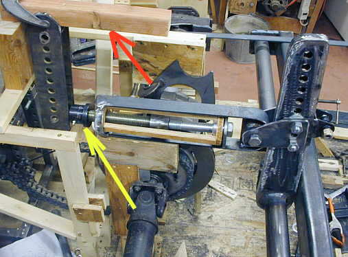
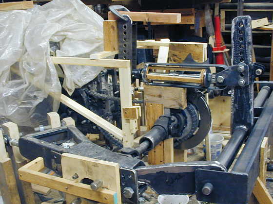
You can see that the left end of the spring is attached to the lever arm via the spring bucket/strap/bracket piece. The jack bolt round nut on the left side (yellow arrow) will be attached to the brackets on the left with the holes in them. They will be attached to the frame top and bottom. There is a space between them so that when you screw the jack bolt, which will pull on the spring from the springs right side, the jack bolt will go between the two upright brackets.
So even though the lever arm is pulling on the spring the spring is always in compression. The piece of wood at the top (red arrow) represents what will be a portion of the top frame rail.
............. .
.
The weight of the car will compress the coil over spring to a certain point. Then the jack bolt can be turned to position the ride height of the car with the spring compressed. Moving the jack bolt to the left will pull the spring and lever arm to the left and will raise the car.
Changing the vertical position of the spring assembly on the lever are and chassis brackets will change the leverage on the coil over spring. This will effect how much the spring compresses along with the initial spring rate of the spring. I want to make sure I can set the ride height so that the control arm, hub, hub lever arm, and the 2 X 4 square tubing with the lever arm tube are all in the same plane for the least air resistance when this is all covered by a fairing with the minimum height to cover these components..The jack bold will let me do that.
Next I have to make the bracket that will mount the round jack screw nut to the frame brackets on the left. I've started on that and hope to be done in a couple more days.
..................................................................Next
Page