...Return To Mine & Other Bonneville Car Construction Pages
.Previous Page...............B'ville Car Index Page.........................Next Page
....Rear Suspension Part II the Outer Lever Arm
.............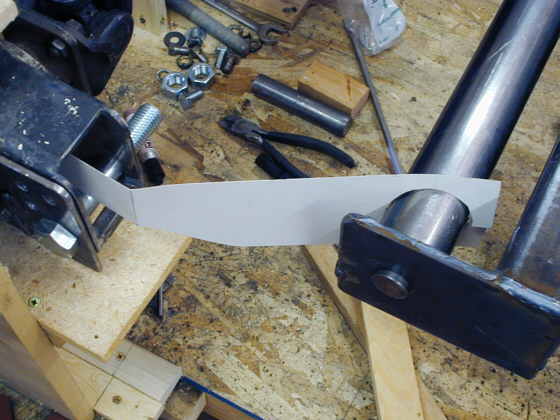
The tubes I finished on the last page will get lever arms on the outboard end going to the hub area and on the inboard end going to the springs/shocks. On this page we will make one of the outer lever arms. I started by making a pattern and trying it out. The lever arm will have a bend to it since the tube couldn't extend further out without running into the sidewall of the tire.
........... .
.
After having problems making the two pieces I wanted identical I finally got the idea to tack them together a couple places and grind them to the final shape together. I had to cut the hole and the outer shape with the cutting torch and then use the die grinder and 4 inch grinder to get them to a final shape.
.............. .
.
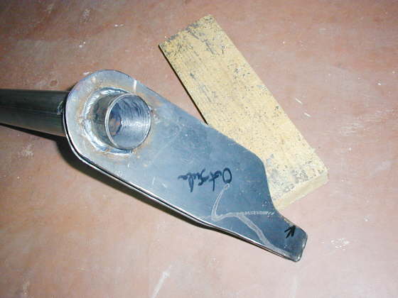
Even though I only had one pattern in the first picture the arm will be made from two pieces of 3/16 inch X 4 inch strap that ended up being about 3 1/2 inches across. You can see the holes are a little elliptical to fit the round tube at an angle. One more so than the other.
.............. .
.
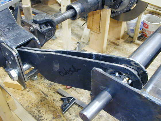
Here are the two pieces tacked to the tube in a trial fit. The one closest to you is straight and the far one has a slight bend to it near the hub.
............... .
.
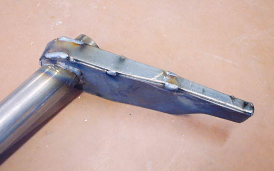
After I was satisfied with the fit I welded them to the tube on the inside and outside of both pieces. I was somewhat worried about distorting the tube and my aluminum bushing no longer fitting. I welded in 1/4 circumference segments around the tube at at time and alternated those welds 180 degrees to each other. When I was finished I cleaned up the inside with a wire brush and lightly with a round grinding stone in the drill. The bushing still fits fine :-).
............... .
.
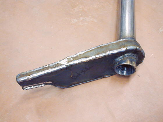
Next I made a paper pattern to box the arm in with some 1/8 inch strap. I transferred the pattern to the strap and ground it to shape with the hand grinder. I tacked it on the arm and wrapped it around the back side and bottom. Then finished welding it all the way around the arm.
............... .
.
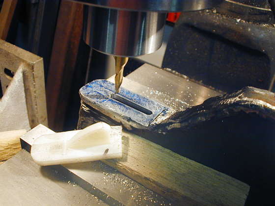
With the arm upside down and in the mill vise I machined the pad where it would ride on the 3/4 inch bolt flat. Then milled a 3/16 inch slot in it for a pad that Speedway sells for their torsion bar arms to do away with metal to metal contact. Actually I took one pad and cut it in half and will use the other half on the other lever arm on the other side of the car.
............... .
.
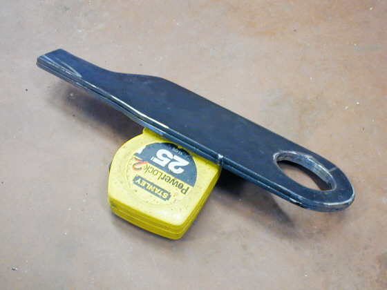
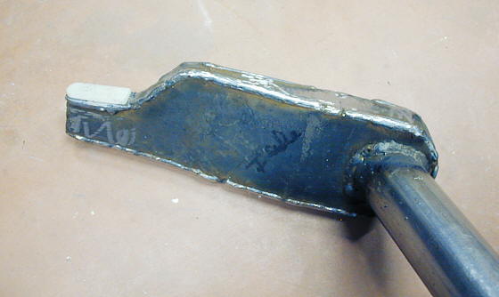
Here is the completed arm upside down showing the pad on the tip.
............... .
.
View of the top of the arm.
............... .
.
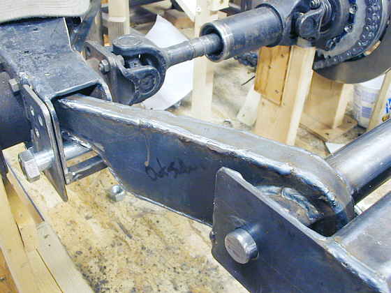
And the arm and tube in position. I moved the hub up and down and so far things
look good. Next up is to make the inner lever arm that will go to the spring/shock and then do the whole thing
over again for the other side.
..................................................................Next
Page