...Return To Mine & Other Bonneville Car Construction Pages
.Previous Page...............B'ville Car Index Page.........................Next Page
............................--- Rear Control Arms Part IV ---
.............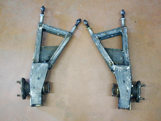
I was able to finish the second (right one) control arm much faster than what it took to do the first one. I'm glad as I hate to have to repeat things. I made a couple subtle changes to it.
........... .
.
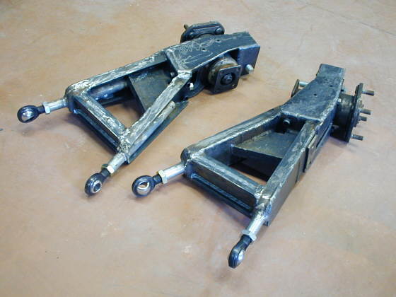
Another view of both rear control arms.
.............. .
.
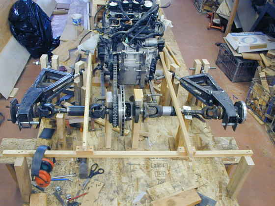
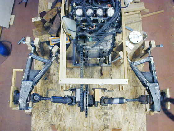
Here they are mounted at their approximate final locations. The wood you see in this and the next picture represent the frame width by the motor and cockpit area. Back here the body will be curving in and these pieces of wood just help me to center things.
............... .
.
I took this overhead view hopefully for some input from one or more of you who knows about U-joints. I moved the center section back about 3/4 of an inch so that the half shafts aren't in a perfectly straight line when viewed from above. I know that a drive shaft's U-joints aren't suppose to point directly at each other. My outer hubs are parallel to the center section, but now the U-joints are operating at a slight angle. Is this the way I want it?
I had one person tell me that they would consume less power if the half shafts were in a straight line at ride height when viewed from both above and from behind. The way I have it here they will be in a straight line when viewed from behind, but not from above.
What do you think?
The consensus, after input from friends, is to move the center section back
forward so that the half-shafts/U-Joints are all in a straight line when viewed from above and from the rear. Most
feel it will take less HP this way and even though the needle bearings in the U-Joint won't want to rotate as much
and could wear quicker, with the limited mileage this car will get, that won't be a major concern. Thanks for the
input guys!!
..................................................................Next
Page