...Return To Mine & Other Bonneville Car Construction Pages
.Previous Page...............B'ville Car Index Page.........................Next Page
.............................--- Rear Control Arms Part II ---
Well August 2005 was taken up with yard and garden work; getting ready and going to Bonneville; and helping Hooley with his Stude. So now it is time to get back to work and I had better stick with it if there is any hope of running this car in 2006.
I'm still trying to get all of the main components (front axle, rear axle, control arms, suspension, etc.) done before starting on the frame. Once all the components are done then I can make a frame to tie them all together and not have to adapt them to a frame. That is the idea anyway.
.............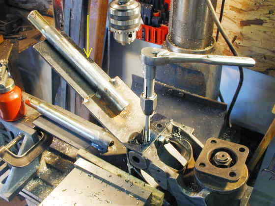
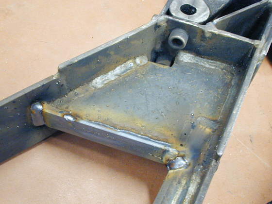
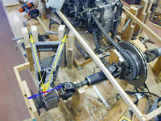
I went back to work on the rear control arms that will locate the outer hub area of the IRS. I added pieces of 3/16 X 3 inch strap that extended to almost the end of the two tubes (see yellow arrow above). Then I drilled and tapped (see above) two more holes for bolts to hold all of this to the original Datsun hub.
.......... .
.
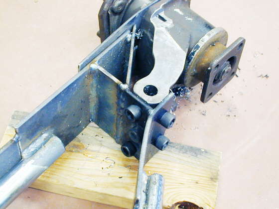
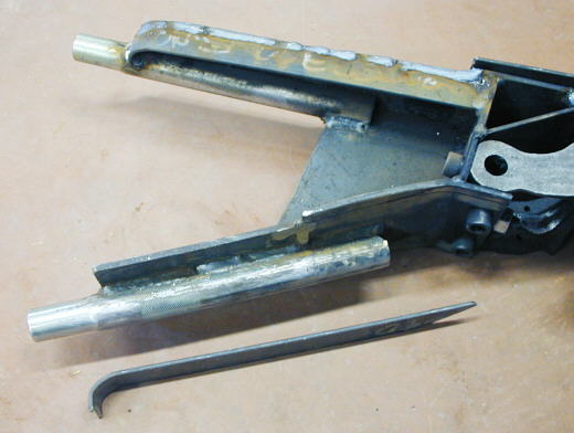
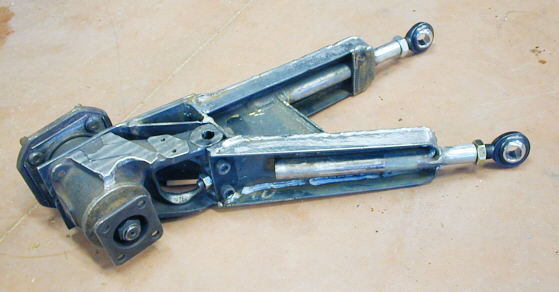
Here you can see the 3 inner and 2 outer bolts that secure this side of the control arms to the hub. I'm trying to triangulate everything as much as possible. I decided that I wanted to add more support to the arms in this area so I made a pattern and cut the piece in the next photo.
............................ .
.
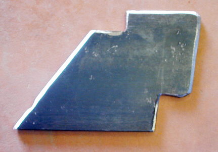
It is cut from a piece of 3/16 X 4 strap. It would be nice to have a plasma cutter, but a cutting torch and grinder will be just fine and doesn't take that much time.
.............. .
.
Here you can see (center of picture) where I welding in the support piece from the last picture.
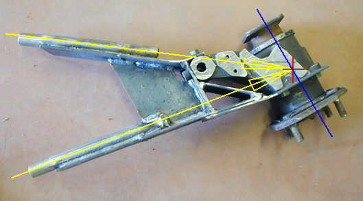
Also I'll try an explain the geometry of how I tried to set this all up. Originally I was going to have the heim joints (not shown, but they go in the left end of the tubes above) perpendicular to the rear axle (blue line) and in line with each other so that a rod would go through both of them. That just wasn't working for me as far as laying it out in a manner that would physically work. Then I looked at a trailer I had that I made back in the 70's from the back IRS from a 60's Datsun (not a Z car) where they had A-arm's off of the frame to locate the outer hubs like I'm doing here. The two control arms of the A-arm had their ends angled in relation to each other like above. I tried that but was having some problems with binding until I realized that the two sides of the A-arm need to intersect the hub at the same point (red + above), which has to also be on the center line (blue line above) of the hub. Each side of the A-arm has to be of the same length from the heim joint to the intersection point (yellow arrows). I will also put some shims on both sides of both heim joints for adjustment of the alignment of the rear wheels/tires. In addition the inner mount for the inner heim joint will have some vertical adjustment and this will allow me to adjust the camber of the wheel/tire. There is a slight amount of toe-in with this setup as the A-arm rises, but I've been told this isn't all bad. You can also look at the last picture on this page to help see what I've been talking about. Hope this is clear.
..........
I welded another piece of strap across the front of the horizontal piece I had welded in during the last step to make a web for even more strength.
...............
Next I wanted to add top and bottom webs to both sides to really add to the rigidity of this piece. They were cut out of 1/8 X 1 inch strap. I cut and fitted them to the desired location and welded them on. Before I welded them on I laid them in place and marked the stepped pieces of strap that were on the sides and cut and ground them to their final dimensions. Then I welded the straps to the sides.
....................
Here is a picture of the straps welded on and you can also see the piece I welded in at the right end of the lower leg in the picture. This picture shows the bottom side of the left control arm.
..............
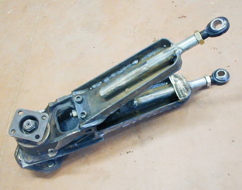
A top view of the left control arm. The top strap that bolts onto the hub (where the brake backing plate would go) is welded every place possible to the rest of the control arm. Hopefully when I'm done when you pull out all of the bolts the control arm will separate from the hub. The bottom strap to the hub will be changed to a thicker/longer one and it will bolt to the hub and to the control arm for disassembly purposes.
............
Another view of the top from the other side. I'll be welding (next picture) a crossmember at the outer ends of the control arms and it will be welded to that cap plate at the end of the upper control arm in this picture.
.........................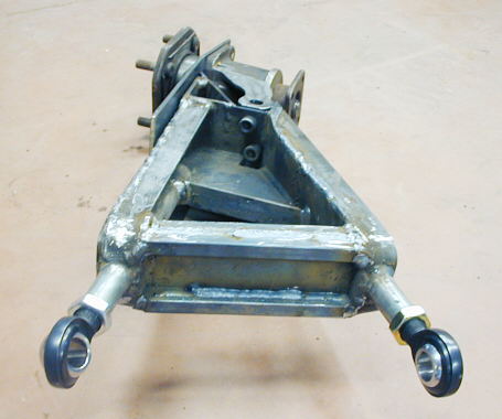
Next I welded a cross piece at the outer end of the control arm. It is a piece of 3/16 X 2 1/2 strap that goes from one side of the control arm to the other. I then welded thin wall 1/2 inch square tubing to both sides of the top and bottom of the strap to make it like an "I-beam".
..............
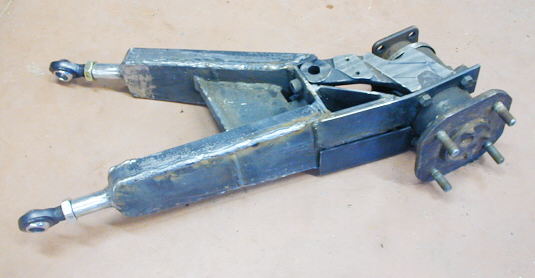
Here is the control arm and hub in place. It looks pretty massive, but at this point has only added about 5 lbs. to the weight of the rear hub. I think it is still lighter than all of the stuff that was on the original hub. If I'm figuring right, about 1/3 of this weight will be sprung weight (where it attaches to the frame) and the rest will be un-sprung weight.
Next I'll be working on the back of the hub (where the vertical plate is)
to make a place where the suspension will pivot on. Then I just have to copy all of this and finish the right control
arm. I have a lot of time in these, but it has been fun figuring them out and building them.
..................................................................Next
Page