...Return To Mine & Other Bonneville Car Construction Pages
.Previous Page...............B'ville Car Index Page.........................Next Page
..........................--- Rear Control Arms Part I ---
The rear suspension will consist of "A-arm" type control arms to
locate the outer hubs and a link type system that will connect inboard coil-overs (or something similar) to the
the outer hubs. Here I will start on the construction of the A-arms.
...............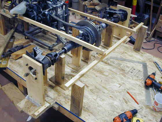
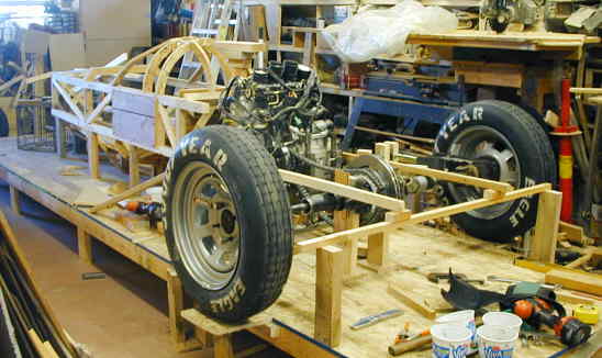
I started by locating the board on top of the vertical 2 X 4's an equal distance from the end of the table I'm building the car on. The two boards coming from the cage area back represent the maximum width of the main frame. It won't be that wide behind the axle, but I wanted these reference points. I also made two end supports for the outer hubs and they locate the hubs at ride height. Right now everything is at ride height. Using the back reference board I was able to get the center section, half shafts and outer hubs all in a straight line and perpendicular to the main frame. I can't emphasize enough how much the build table helps to do all of this. Especially since I can screw supports anywhere I need them and get reference measurements off of the center line going down the middle of the table or off any of the edges.
............ .
.
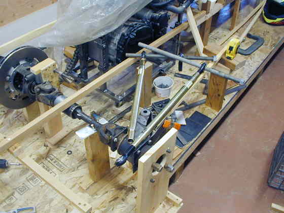
I purchased some tubing with swedged ends that are threaded for 3/4 inch heim joints (see my parts list on the main menu). I put some heim joints in one end and using some 3/4 inch all thread rod started to play with attachment points for the a-arms. This helped me to visualize what was going to happen during suspension travel, which will be about 1 to 1 1/2 inches of compression and 1/2 inch of rebound.
............... .
.
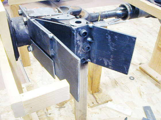
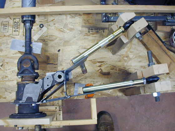
I added some more pieces to the control arm brackets I had started on the last web page. To the right is a piece that for the moment is tack welded (will be fully welded later) to the last piece I made. It will also be drilled and bolted to the end of the hub arm. To the left is a piece of 3/16 X 4 inch strap that is tacked (fully welded later) to the top piece of the control arm bracket. It will be bolted to the bottom piece later so that all of this will be able to be unbolted from the outer hub.
There is a vertical board holding the hub at ride height (left side of the picture). From that board going to the bottom left of the picture is a 1 X 2 with another short 1 X 2 at 90 degrees. The end of that short 1 X 2 is where the inner surface of the tire will be. I put it on there to make sure all of the brackets and control arms where going to clear the tire. You can see the tire clearance in some of the pictures below.
............... .
.
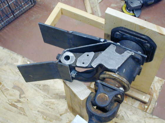
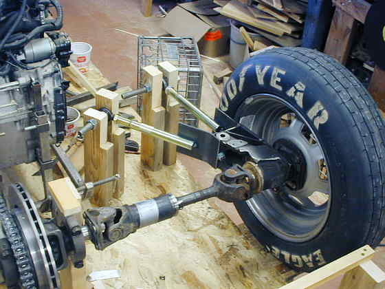
Here is another view and you can see where the angled piece will be drilled and bolted to the arm on the hub right above the 2 X 4. I will tap holes in the arm. All of this later will get a flat piece on top with some other bracing to tie it all together. The suspension will pivot on a pin to the right side of the hub that will be added later.
...............
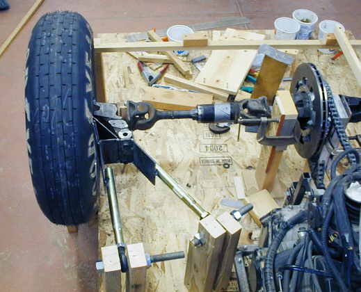
I cut one of the swedged tubes in half and used the end with the right hand 3/4 inch threaded heim joint on the leg of the a-arm to the bottom and the one with the left hand heim joint to the top of the picture. I tack welded these on the control arm bracket level with the ground and they are supported at the heim joint end at ride height.
...............
The two control arms both angle in to the same point on the centerline of the outer hub and are the same length from that point back to the center of the heim joints. This seems to be working and the rear seems to pivot so there is only a slight amount of camber change and a little toe-in under compression.
...................
This is just the beginning on these arms. There will be bracing from the top and bottom of the hub brackets to the area of the swedged tubing near the heim joints and also cross bracing for the whole assembly. I just wanted to make sure at this point my ideas were going to work.
..............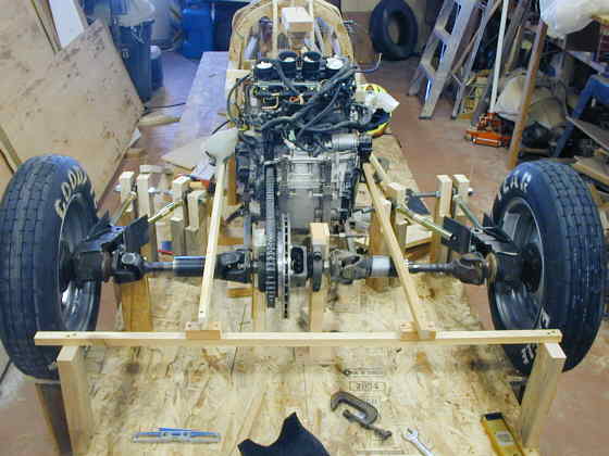
A view from the rear showing the left side also finished to this stage. The idea is for the a-arms, outer hubs and half-shafts to all fit into a vertical plane of less than 7 inches during suspension travel. This 7 inches will be covered by pods sticking out from the body that will run down the car from the front to rear. I wanted to get the tires/wheels about 12 inches out from the body to keep clean air going down the body sides and along the tops and bottoms of the pods. It looks like the inner plane of the tires will be about 13 inches out from the body sides, so that is accomplished.
...............
If I squint real hard I can start to see a LSR car here. Later all of this
rear-end assembly and motor will move about 2 feet further back from the cage. I'll need room there for the gas
tank, intercooler ice tank, intercooler and other items. I had the motor up against the cage to help determine
the final height of the car so that I would have room for the inlet tract for the motor.
..................................................................Next
Page