...Return To Mine & Other Bonneville Car Construction Pages
.Previous Page...............B'ville Car Index Page.........................Next Page
...............................--- Seat & Roll Cage Part III ---
Well another step back and two forward. Here you will see where I redesigned the cage by my helmet and also the lower crossmembers. I can't stress enough how relatively easy it has been to make these changes in wood and with the surface plate. With the centering line down the surface plate and it's parallel sides it is very fast and easy to center components with the use of a square. If you ever build a car from scratch like this be sure and do yourself a favor and take a couple hours to build a surface plate. It also gets the car up higher where it is easier to work on.
............. .
.
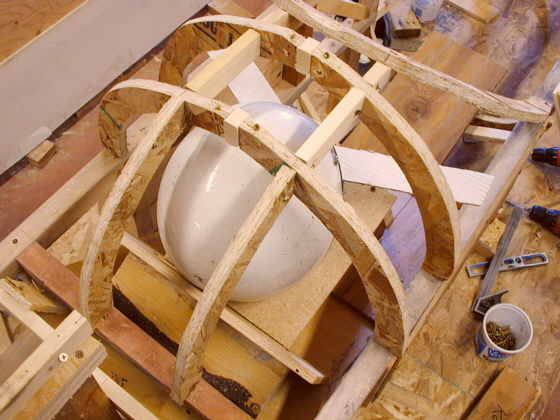
I didn't like just the one front helmet hoop and one behind it, so I re-did the top of the cage and put in a second hoop going cross-wise.
............ .
.
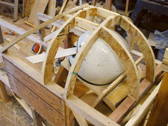
I feel better about this configuration. The piece of angled cardboard in these pictures represents my field of vision. It has to be at least 120 degrees. The cardboard is cut at 130 degrees.
................................. .
.
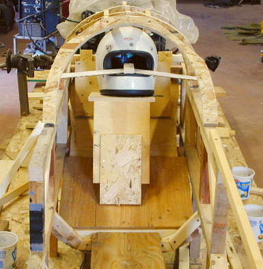
After I get a newer helmet (mine is from the 70's and a lot smaller physically than new ones) I'll finalize the lateral distances from the helmet to the helmet hoops. I want it closer than this. If you have a newer larger helmet (outside is larger than the one in the picture) that is out of date for racing and want to sell it cheap, loan it to me or donate it please contact me. I need a size 7 or larger.
............ .
.
Here you can see the diagonal bracing between the vertical uprights. The piece of paneling on this side and the other side will be 1/4 inch steel plate. This will allow me some room out past the inside plane of the main frame rails. I won't need it all, but it will give some insurance room if I ever have a larger driver in the car. I will make the seat sides as tight as I can to support my shoulders and hips from lateral movement.
...........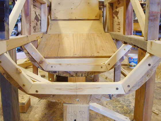
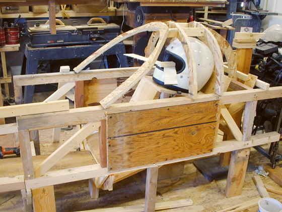
On the previous page I had decided to go with bent tubing for the bottom frame crossmembers. Re-thinking that I decided I could go with .120 X 2' square tubing if I cut it at a couple angles. The 1 X 2's here represent what will be 2" square tubing. I left the rounded wafer board in place to represent the final body shape on the bottom of the car. I will use "diamond" shaped pieces of 1/8 inch steel across all of the final weld joints in this area to reinforce them. In the picture you can also see the room gained with the steel plates in the shoulder area on the sides.
...................................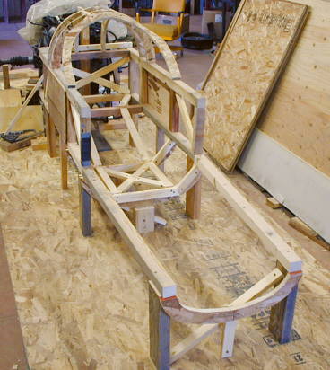
This picture shows the finished driver compartment down to my butt area (where the "X" bracing is). I've also started out into the foot well area.
..............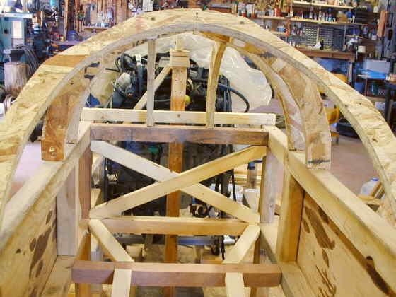
A view of the "X" bracing at the back of the cage area along with some of the bracing under my back and head area.
..........................................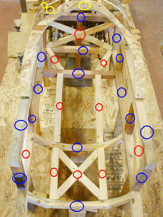
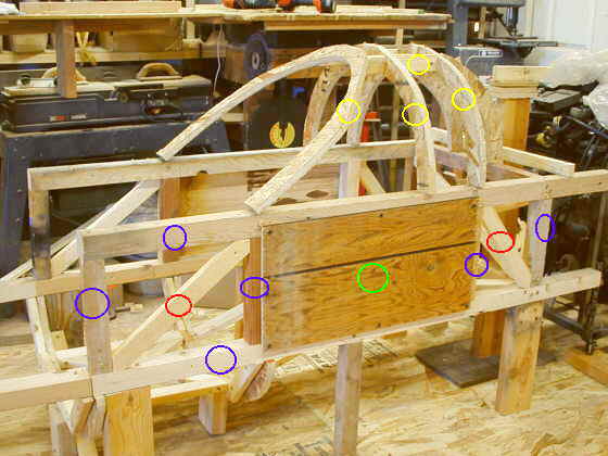
This is a picture looking down into the cage. All of the frame members with the "blue" circles would be .120 X 2 X 2 square tubing. The "red" would be .120 X 1 1/2 X 1 1/2 square tubing. The "yellow" would be 1 5/8" DOM tubing. The two near bottom cross members would be cut and welded to give a semi circular appearance to get me down in the car. They would have "diamond" lap gussets on all of the welded joints. The near "X" area would be where my butt is. The 1 1/2 members in the center going back and sloping up would be behind my back.
...............
Here is a side view with the same colors applying (Blue 2", Red 1 1/2",
Yellow 1 5/8" and the panels with the green circle would be 1/4" plate and my shoulders would be inside
of those. The rounded "wafer" board on the bottoms represents the lower body contour.
..................................................................Next
Page