...Return To Mine & Other Bonneville Car Construction Pages
.Previous Page...............B'ville Car Index Page.........................Next Page
.................................--- Seat & Roll Cage Part I ---
Wanting to get the front end, rear end and seat area done before I started making the frame I decided to work on the driver's compartment some. My goal here is to make it as small as possible and then make the body conform to it as much as possible. Originally I wanted to make the driver compartment kind of universal so someone else could also drive the car. I now don't think this is a good plan with this type of car. I'm making it to fit me and will have to deal with the problem of a different size driver if that ever happens.
.................. .
.
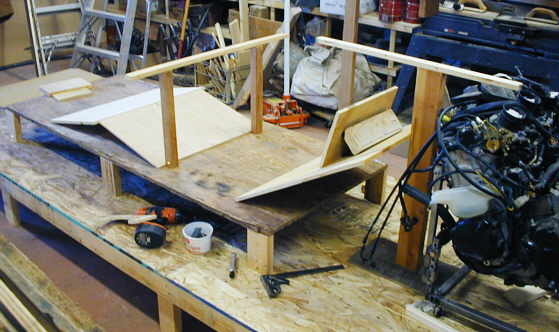
I started by building a platform that I felt would be at ride height in the car for the bottom of the seat. In front of the motor I put an up right with a horizontal piece out from it. The bottom of that piece will be the top of the car over the motor, so I want my helmet to fit in under it. I started putting in sloping sheets of plywood to represent the seat back and head rest. I experimented with different angles. The two angled ones up front were nice to support my legs, but I can't use them as they interfere with entry and exit. The two uprights in the middle with the cross piece are there to help me visualize how high the front of the car can be still give me a view out the front down course. It also helps me to figure out if I can get into and out of the car with my legs trapped forward of it. The motor won't be this close to the seat in the final car. I have them close together at this point to determine the car height.
............... .
.
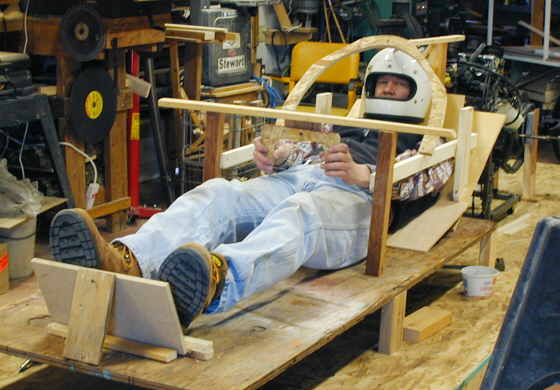
Here I have the seat back finalized and I found that having a stop for my heels helped in making my legs more comfortable in their bent position. I need to have them bent so that I can operate the foot pedals better. Due to the small amount of room up by the steering wheel I might not be able to have a hand brake lever there. If so I will have to have gas, brake and clutch pedals for my feet. It looks like there is room for all three even with my big feet. In this picture you can see the front hoop of the roll cage and also a mock up of the steering wheel. I had my wife put on the helmet and get "in" so I could see how thinks looked. She couldn't believe I actually wanted to get into something that small. As soon as it is more closed in I'm sure I'll never get her in it, even standing still. Yet she still supports me in this, so that is the important thing.
................. .
.
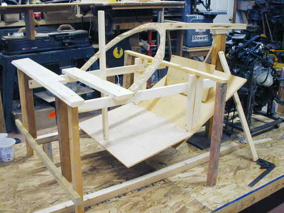
I wanted to mock up the top and bottom frame rails, which are also part of the cage in the driver's compartment. To do this I needed to get rid of the platform I was using in the last two pictures. In this picture I've built some temporary uprights and crossmembers to hold the seat in position while I remove the platform (which has been removed in the picture).
................. .
.
I replaced the temporary pieces in the last picture with the new pieces of 1 X 2's that I'm using to represent the frame rails, which will be .120 X 2 X 2 square tubing. There will be more uprights and diagonal bracing added as I continue working on this part of the car. I will use the 2 X 2 square tubing in the driver's compartment, from in front of my feet to behind my head area to meet the safety requirements. The rest of the frame will probably be .120 X 1 1/2 X 1 1/2 square tubing for the main frame rails. I would have like to use round tubing, but I'm not set up to bend it properly.
.................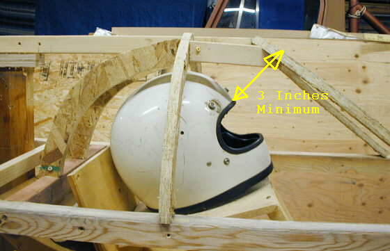
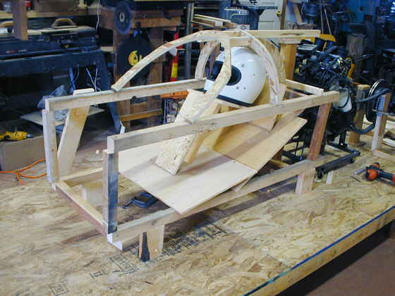
I made a stand that holds the helmet about in the same position as when I'm in the car. I was somewhat confused on how to measure the 3 inch minimum helmet clearance off of the front hoop of the cage. John Bjorkman (SCTA Special Construction Category Chair) cleared that up for me, thanks John. What you do is locate your front hoop and lay something flat on it and measure back perpendicular from that plane to the helmet. The closest any part of the helmet can be to that plane is 3 inches.
.................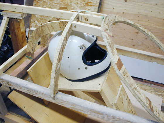
I cut out a front hoop (probably not the final shape) and hooked it to the 1 X 2 that was coming from the motor and which represents the top of the car. I then made some side hoops and back hoops from wafer board.
.................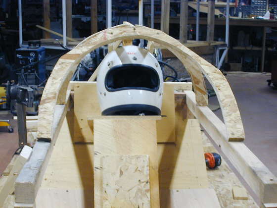
Looking from the front I have more clearance on the side of the helmet than I want. I'm right at the 4 inch maximum lateral head movement allowed. The front hoop will stay like it is, but I'm going to look at pinching in the top frame rail behind the front hoop to move the side hoops in a little. Another thing that has to be added to the final cage is .125 X 1 inch helmet-retaining strap going around the inside of the helmet hoops.
.................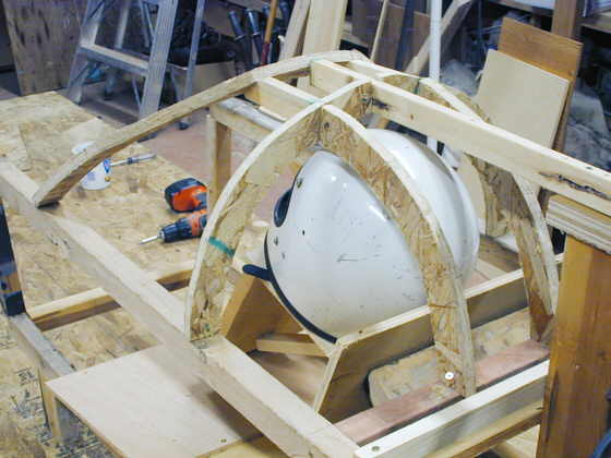
Another picture of this area.
.................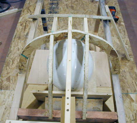
And a final picture from the rear. The 1 X 2 in the middle of this picture is only for construction purposes and doesn't represent a final tube in the helmet part of the roll cage. The other pieces will be replaced with .120 X 1 5/8 inch mild steel tubing.
I did all of this in one day and I can see I want to change some of it, but this gives me a start. Using the wood surface plate has sure worked out great. I can make quick changes to what I'm doing by just making wood supports of the correct length and using the screw gun with "grabber screws" of different lengths. I'm glad I'm mocking the frame up with wood as it will hopefully save a lot of screw-ups. When I start the final steel frame I hope to keep the wood one in place and replace one piece at a time with the steel replacement.
..................................................................Next Page