...Return To Mine & Other Bonneville Car Construction Pages
.Previous Page...............B'ville Car Index Page.........................Next Page
.................--- Pillow Blocks for Carrier Bearings ---
.................. .
.
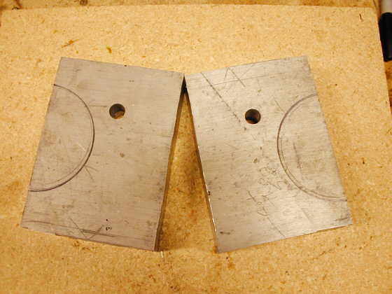
I needed to make two pillow blocks to support the ball bearings that are on both ends of the carrier that has the rear sprocket and disc brake rotor attached to it. The carrier bearings were supported in the original Datsun Z differential with a machined area in the case itself and with bearing caps that held the bearings in the case. Since I will run the carrier out in the open and not in the differential case I had to come up with a way to hold and support the carrier bearings.
I'm also switching from the tapered roller bearings to sealed ball bearings of the same size. They will turn easier than the tapered bearings and since there is no longer a side load on the bearings (no pinion and ring gear) I can go to the ball bearings.
The following is how I made the pillow blocks for the bearings. I had a piece of scrap aluminum about 4 inches wide by about 12 inches long and 1 1/2 inches thick. I cut that piece in half (see above picture) using my wood band saw that I had recently converted to a metal band saw.
................. .
.
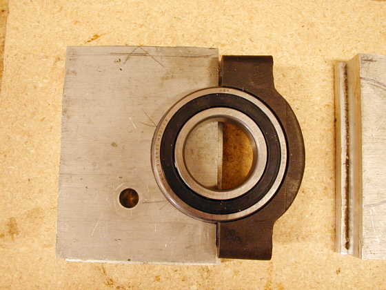
Here I'm trying to figure out if I'm comfortable with all of this and how things will mount up and where I'll have to bore the aluminum. I decided to use the caps that held the original tapered bearings in the differential housing and the blocks will take the place of the other half of the bearing support that was the differential housing.
................. .
.
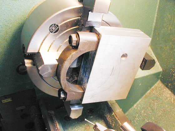
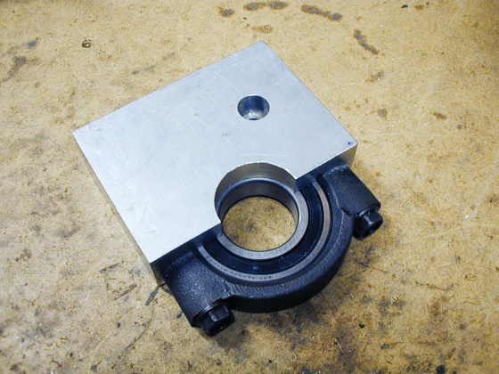
Next I squared the rough cut blocks up on the mill to 4 inches by 5 1/2 inches. I also drilled and tapped holes for the metric cap screws from the original differential that hold the bearing cap in place. Then (picture above) I mounted all of that in the lathe using my 4 jaw chuck. I centered it with a dial test indicator locating off of the bearing surface in the cap.
................. .
.
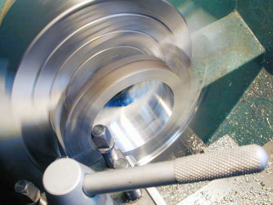
This is a picture of the block/cap turning in the lathe at a couple hundred rpm while I'm boring out the center of it for the bearing to fit into.
..............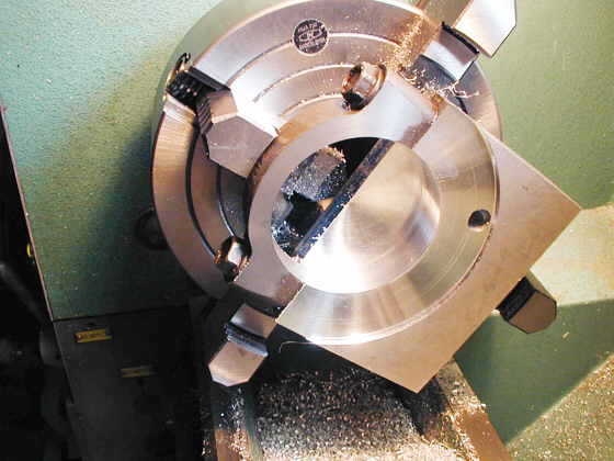
I turned a large radius to a 1/8 inch depth into the block flush up against the bearing cap. I wanted to move the cap more towards the center for strength. That meant I had to relieve this area so there would be clearance for the bolts that hold the rear sprocket to the carrier. The next step was to bore the center out to receive the bearing. I bore that area just deep enough to house the bearing below the cap. The outside of the block past the bored area will act as a retainer to keep the whole bearing assembly centered in the final frame of the car.
................................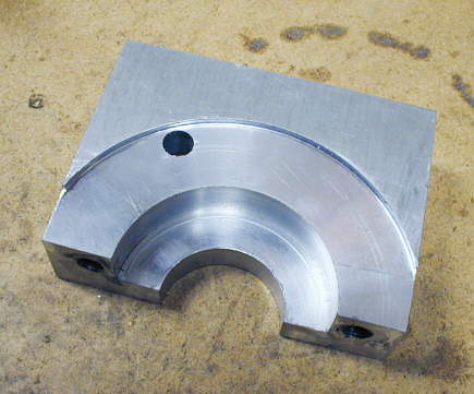
The finished pillow block from the inboard side. You can see where I had to continue boring the center out to make room for the output shaft that the 1/2 shafts attach to.
.................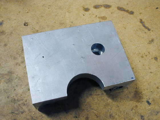
Pillow block from the outboard side. The hole in the block was already in the scrap piece I had and probably won't be used for anything.
.................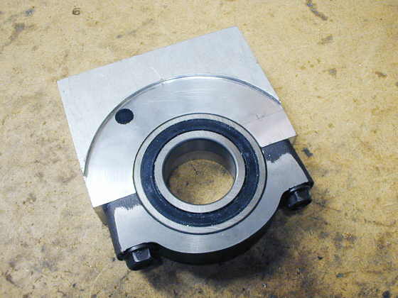
A view with the bearing in place and held in by the cap. This is an interference fit and the cap/block combination is a little smaller in diameter than the bearing. With the bearing clamped in you can't turn the outer race of the bearing.
.................
A view of the outer side of the block. There will be holes drilled and tapped later into the block to hold it to the frame. The mounts on the frame will be built in such a way that they will cradle and support the block and add to the strength of the block.
.................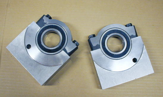
I finished the second one as you can see in the picture above. I'm very happy how these turned out. These are the most complicate pieces I have had to make with my mill and lathe to this point. Getting them set up (centered) to turn and the close tolerances I had to make them too were something I had really worried about.
..................................................................Next Page