...Return To Mine & Other Bonneville Car Construction Pages
.Previous Page...............B'ville Car Index Page.........................Next Page
................-- Bottom Rear Body Mounts - Part I --.................
.................. .
.
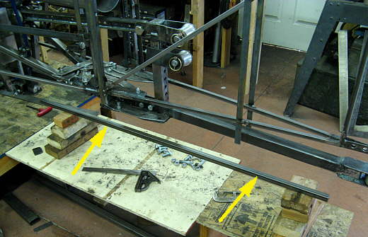
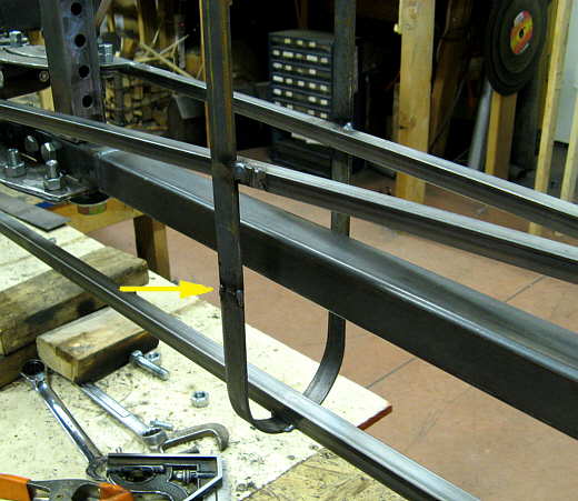
Some of the fabrication work on this page was done in advance of the work shown on page 127 where I did the rear portions of the side pods. The 1/2 inch X 1/2 inch square tubing (arrows) was blocked into place where the bottom of the car's body work will be. The bottom of the car will be 6 inches off the ground from near the front all the way to the back of the car. The square tubing was blocked at 6 and 1/8 inches to all for some other parts that you will see below. The square tubing......
.................. .
.
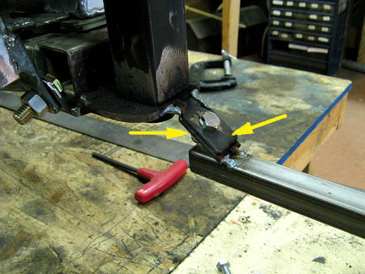
.................... was attached at the forward edge with two tabs (arrows) to the existing car there. Later I had to cut the back (left tab) off and put it in front of the right one (right arrow). This change needed to be made as this body mounting assemble that is being made has to slide straight off the rear of the car and the one tab being behind the other stopped that from happening.
.................. .
.
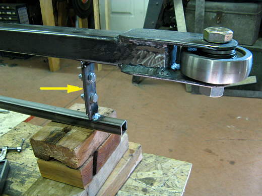
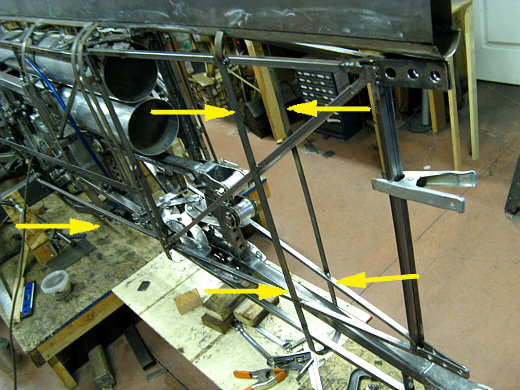
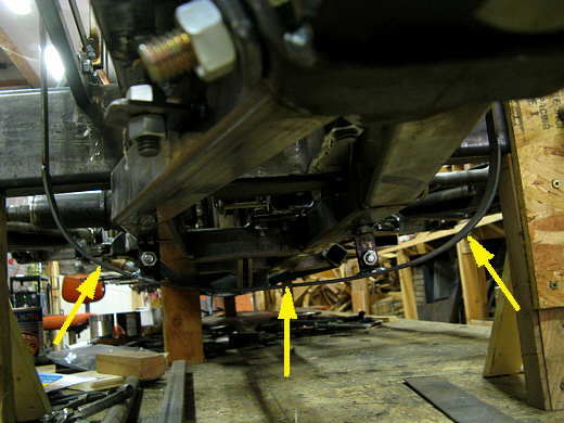
The rear most part of the square tubing was attached to the push bar with two tabs (arrow). With the square tubing defining the bottom of the car vertical ribs had to be made next.
.................. .
.
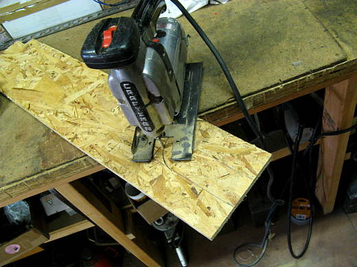
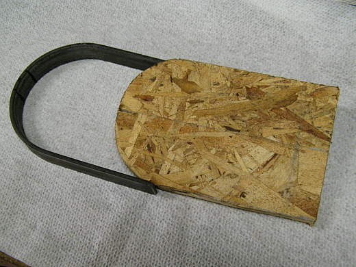
I laid out the shape of one on a piece of scrap wafer board and cut it out......
.................. .
.
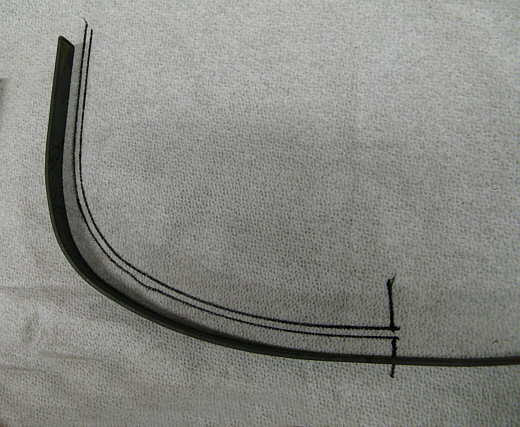
.........then bent a piece of 1/8th X 3/4 strap around it and ........................
.................. .
.
.................. welded it to the square tubing on the bottom, which is actually 6 and 1/8 inches off of the build table. The upper end of the new piece was cut back to the correct length to weld it to the vertical chute door mounting pieces (arrow). Later it will be cut loose from the door, but for now the door ones help to locate these ribs in the right spot.
.................. .
.
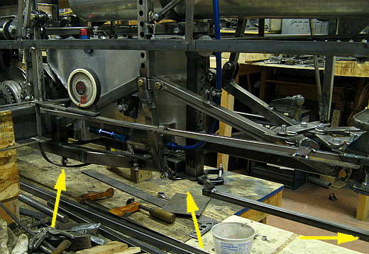
The group of arrows at the right point to all of the pieces that will define the cars cross-section at that point. The left arrow points to were another rib has to be built and placed to define the bottom of the car in that area.
.................. .
.
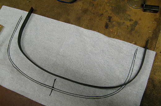
Another piece of strap was bent that meet the existing forward top body mounts made starting on page 124. It was bent down and under so that the bottom of it would be 6 inches off of the ground and roughly the shape of the bottom of the car at the firewall (page 115). The shape was transferred onto some paper towels and then flipped over and .............
.................. .
.
................ drawn again for a mirror image. Then the other side was also bent to fit the pattern that had been made from the shape of the one side. I bend most all of this in the vise by opening the jaws a couple inches then putting the strap in horizontal to the ground and bending then moving a 1/4 to 1/2 inch and bending a little more. I usually over bend then just unbend it to fit the pattern. You can do this almost as quick as I just explained it.
.................. .
.
Here it is installed on the bottom of the car with some of the tabs that I made on the previous page.
.................. .
.
Now there is a forward locating rib on the bottom (left arrow) and a rear one (just to the right of the right arrow). On the next page one will be made to go between them (middle arrow).
..............................................................Next Page